Carbon fibre cloth for gaseous diffusion layer of fuel cell

A technology of gas diffusion layer and carbon fiber cloth, which is applied in the parts of fuel cells, fuel cells, electrical components, etc., can solve the problems of inability to achieve optimization, non-uniformity, and decreased water discharge.

Inactive Publication Date: 2008-12-24
程显军
View PDF0 Cites 19 Cited by
  • Summary
  • Abstract
  • Description
  • Claims
  • Application Information

AI Technical Summary

Problems solved by technology

However, this duplication method has the difficulty of increasing the number of processing steps
Also, the use of a water-repellent layer-forming coating formulated to a suitable high viscosity to suppress the above-mentioned penetration is being studied, but no significant inhibitory effect has been obtained.
[0014] For the previous carbon fiber cloth used as the base material of the gas diffusion layer, due to the rigidity of the surface of the carbon fiber bundles, it is impossible to make the uniformity of the intersecting gap of each bundle through weaving, and because of the surface slidi

Method used


Image

  • Carbon fibre cloth for gaseous diffusion layer of fuel cell

Examples


no. 1 example

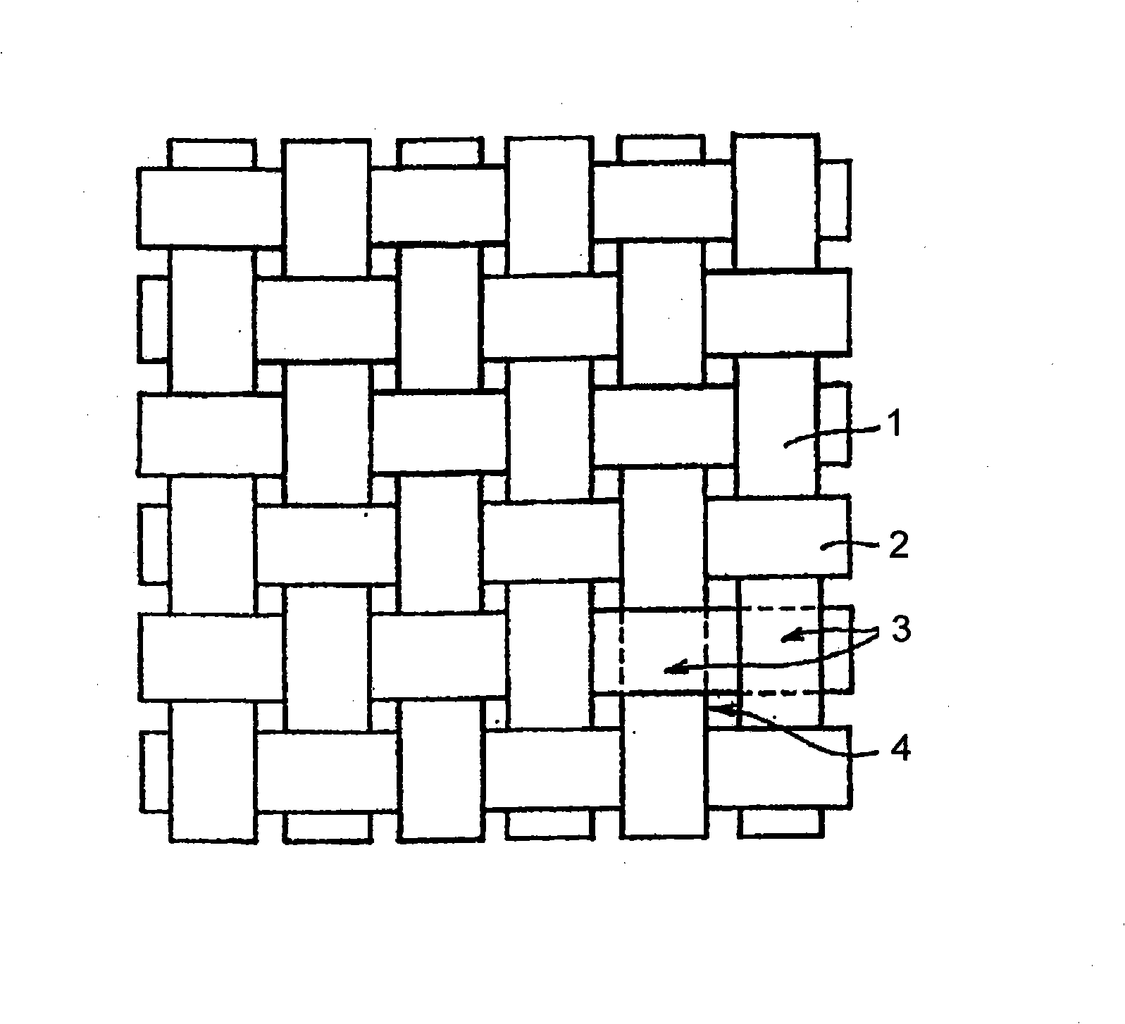
[0042] Pre-oxidized fibers are made from polypropylene nitrile (PAN) fibers after being pre-oxidized in a pre-oxidation furnace at a temperature of 300°C; after crimping and shredding, they are made into tops, and then yarns are made into yarns through the textile process, and then woven into longitudinal and transverse yarns. Pre-oxidized fiber cloth with intersecting yarns, with a thickness of 0.60 mm, made of double yarns with a thickness of 0.450 mm and a double yarn with a thickness of 0.450 mm. The density of the longitudinal yarns is 17.7 strands / cm The yarn density is 15.4 strands / cm; the pre-oxidized fiber cloth is subjected to cooking and heat treatment; then enters the carbonization furnace for the first carbonization at 500°C; then enters the carbonization furnace for the second step of medium temperature carbonization at 1000°C; finally enters the carbonization furnace for Carbon fiber cloth is obtained by high temperature carbonization at 1500°C. The head weight ...

no. 2 example

[0045] The manufacturing process step of the second embodiment is basically similar to that of the first embodiment, except that the thickness of the pre-oxidized fiber cloth is 40 mm, and the thickness of the double yarn is 0.445 mm and the thickness of the double yarn is 0.445 mm. Made of 0.445mm horizontal yarn, the longitudinal yarn density is 15.7 / cm, and the horizontal yarn density is 15.4 / cm; the weight of carbon fiber cloth is 80g / m 2 ; Thickness 0.20mm; Density 400g / cc.

[0046] Table 1 The following are the relevant technical parameters of carbon fiber cloth used in the fuel cell gas diffusion layer:

[0047] project


PUM

PropertyMeasurementUnit
Thicknessaaaaaaaaaa
Thicknessaaaaaaaaaa
Densityaaaaaaaaaa

Abstract

A carbon fiber cloth for the gas diffusion layer of a fuel battery is characterized in that polyacrylonitrile (PAN) fiber is pre-oxidized at a temperature of 300 DEG C in a pre-oxidizing furnace to obtain the pre-oxidized fiber; the pre-oxidized fiber is prepared into the pre-oxidized fiber cloth with the thickness of 0.60 mm by adopting the conventional process, wherein the longitudinal yarn is formed by double-yarn with a thickness of 0.445 mm to 0.450 mm, and the transverse yarn is formed by double-yarn with a thickness of 0.445 mm to 0.450 mm; and the density of the longitudinal yarn is 15.7 to 17.7 strands / cm, and the density of the transverse yarn is 15.4 strands / cm; and the pre-oxidized fiber cloth is prepared into the carbon fiber cloth by the secondary carbonization, wherein the areal weight is 80 to 170 g/m<2>; the thickness is 0.20 to 0.3 mm; the density is 0.362 to 400 g/cc; the carbon content is 99.5%; the interlayer shearing force is 5.0 mpa; the tensile strength is 192.5; the tensile modulus is 26.6 Mn/cm<2> (msi); the flexure strength is 50 Mpa and the bending modulus is 7.5 Gpa. The prepared carbon fiber cloth is optimized and has a smooth surface.

Description

technical field [0001] The invention relates to the field of carbon fiber composite material manufacturing, and relates to a carbon fiber cloth used for a gas diffusion layer of a fuel cell. Background technique [0002] The gas diffusion layer material plays a role in supporting the catalyst layer and stabilizing the electrode structure in the electrode. It also provides fuel gas channels, electron channels and drainage channels for the electrode reaction. The influence of different diffusion layer materials on the structure, manufacturing process and performance of the electrode Also vary. Carbon fiber paper (carbon paper), carbon cloth, non-woven fabric and carbon black paper are commonly used electrode materials. [0003] At present, some gas diffusion layers use carbon paper, and some use carbon cloth materials. They not only have a uniform porous thin-layer structure, but also have good electrical conductivity, good chemical stability and heat resistance, and the fla...

Claims


Application Information

Patent Timeline
IPC IPC(8): H01M8/02H01M4/86D03D15/00D03D15/12D01F9/22D03D15/275D03D15/283H01M8/0234
CPCY02E60/50
Inventor 程显军
Owner 程显军
Why Eureka
Try Eureka