Stack for fuel cell, and fuel cell
A fuel cell and battery technology, which is applied to fuel cells, fuel cell groups, fuel cell components, etc., can solve problems such as impeding liquid flooding resistance, unable to reduce pressure loss deviation, etc., to reduce pressure loss, reduce deviation, The effect of high flooding resistance
- Summary
- Abstract
- Description
- Claims
- Application Information
AI Technical Summary
Problems solved by technology
Method used
Image
Examples
Embodiment 1
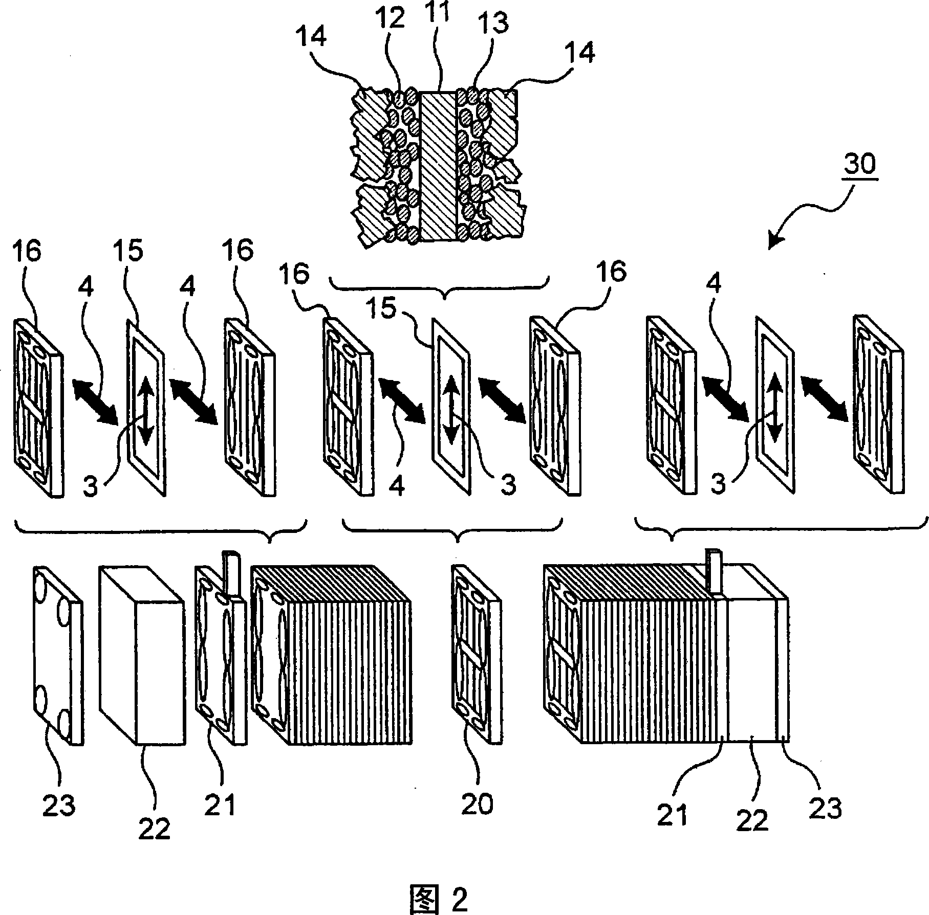
[0089] First, a method of manufacturing the MEA included in the fuel cell stack according to Example 1 of the present invention will be described. On both sides of a polymer electrolyte membrane (Nafion 112 manufactured by Dupont), a catalyst in which platinum is supported in acetylene black powder is coated to form a catalyst layer, and a gas diffusion layer with a carbon fiber woven fabric as a base material is arranged on the outside. The carbon fiber fabric has a plain weave structure, and GDL-1 (Gas Diffusion Layer Base Material-1) shown in Table 2 was used.
[0090]In addition, the characteristic data related to the elongation of two kinds of gas diffusion layer base materials GDL-1 and GDL-2 having different characteristics are shown in Table 2. The value obtained by dividing the displacement of the fabric under the condition of a load of 10 N when a tensile load is applied to a carbon fiber fabric with a width of 25 mm at a distance between chucks of 100 mm by the init...
Embodiment 2
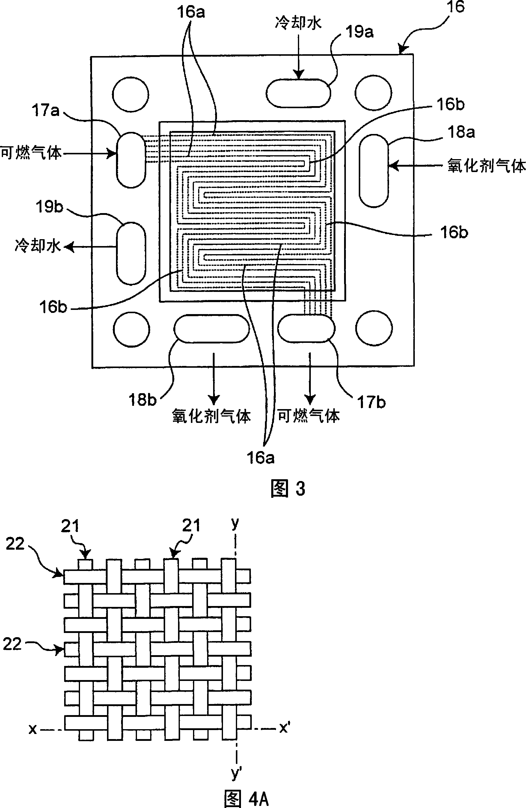
[0100] Next, the fuel cell stack of Example 2 will be described. In the same manner as in Example 1, an MEA and a separator were produced, and the warp arrangement direction of the carbon fiber woven fabric of GDL-1 shown in Table 2 was arranged perpendicular to the main direction of the gas flow path of the separator to produce a single cell. In the same manner as in Example 1, 50 of these single cells were stacked, stainless steel current collector plates and insulating plates of electrically insulating materials were arranged at both ends, and end plates were arranged and fixed with fastening rods to manufacture a stack for fuel cells. That is, in Example 2, as shown in Table 2, the gas diffusion layer base material (GDL -1) the stack.
[0101] For the solid polymer fuel cell equipped with the fuel cell stack of Example 2 prepared in this way, the conditions of Example 1 were used to measure the flooding resistance, the average pressure loss and standard deviation in the s...
Embodiment 3
[0103] Next, the fuel cell stack of Example 3 will be described. In the same manner as in Example 1, an MEA and a separator were produced, and the warp arrangement direction of the GDL-2 carbon fiber woven fabric shown in Table 2 was arranged parallel to the main direction of the gas flow path of the separator to produce a single cell.
[0104] In the same manner as in Example 1, 50 of these single cells were stacked, stainless steel current collector plates and insulating plates of electrically insulating materials were arranged at both ends, and end plates were arranged and fixed with fastening rods to manufacture a stack for fuel cells. That is, in Example 2, as shown in Table 2, the gas diffusion layer base material (GDL -2) the stack.
[0105] For the solid polymer fuel cell equipped with the fuel cell stack of Example 3 prepared in this way, the conditions of Example 1 were used to measure the flooding resistance, the average pressure loss and standard deviation in the ...
PUM
| Property | Measurement | Unit |
|---|---|---|
| current density | aaaaa | aaaaa |
| particle diameter | aaaaa | aaaaa |
| freezing point | aaaaa | aaaaa |
Abstract
Description
Claims
Application Information
 - R&D
- Intellectual Property
- Life Sciences
- Materials
- Tech Scout
- Unparalleled Data Quality
- Higher Quality Content
- 60% Fewer Hallucinations
Browse by: Latest US Patents, China's latest patents, Technical Efficacy Thesaurus, Application Domain, Technology Topic, Popular Technical Reports.
© 2025 PatSnap. All rights reserved.Legal|Privacy policy|Modern Slavery Act Transparency Statement|Sitemap|About US| Contact US: help@patsnap.com


