Transmission method for upstream channel measuring reference signal

A transmission method and reference signal technology, applied in the transmission system, digital transmission system, pilot signal allocation and other directions, can solve the problem that the base station is difficult to measure the uplink channel, cannot send the SRS signal, and the starting position of the SRS signal cannot be correctly determined, etc. question

Active Publication Date: 2008-12-24
ZTE CORP
View PDF0 Cites 102 Cited by
  • Summary
  • Abstract
  • Description
  • Claims
  • Application Information

AI Technical Summary

Problems solved by technology

[0026] Currently, for n RRC There is no clear solution on how to determine it. The initial position in the frequency domain obtained by the existing scheme is incorrect. Therefore, the initial position in the frequency domain of the SRS signal cannot be correctly determined, which leads to the fact that the UE cannot be in the correct initial position in the frequency domain. Send the SRS signal to the base station, and then the base station is difficult to accurately measure the uplink channel

Method used


Image

  • Transmission method for upstream channel measuring reference signal
  • Transmission method for upstream channel measuring reference signal
  • Transmission method for upstream channel measuring reference signal

Examples


no. 1 example

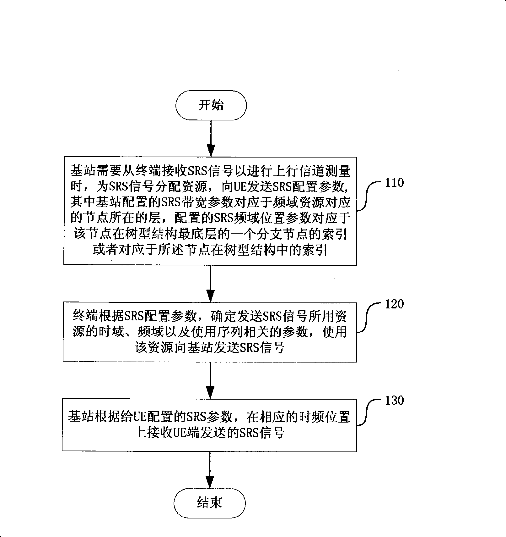
[0067] figure 1 A flow chart of the base station sending SRS configuration information and the UE sending SRS signals according to the configuration information is given, including the following steps:

[0068] Step 110, when the base station needs to receive the SRS signal from the terminal for uplink channel measurement, allocate resources for the SRS signal, and send SRS configuration parameters to the UE;

[0069] The SRS configuration parameters are divided into three categories, one is the parameters related to the time domain position of the SRS signal, the other is the parameters related to the sequence used by the SRS signal, and the other is the parameter related to the frequency domain position of the SRS signal. The first two types of parameters are outside the scope of the present invention. Some of the cell-specific parameters are broadcast in the cell, while the UE-specific parameters are configured through high-level signaling.

[0070] The parameters related...

no. 2 example

[0088] The flow of the method in this embodiment is the same as that in the first embodiment, and only the method for determining the initial position in the frequency domain will be introduced below.

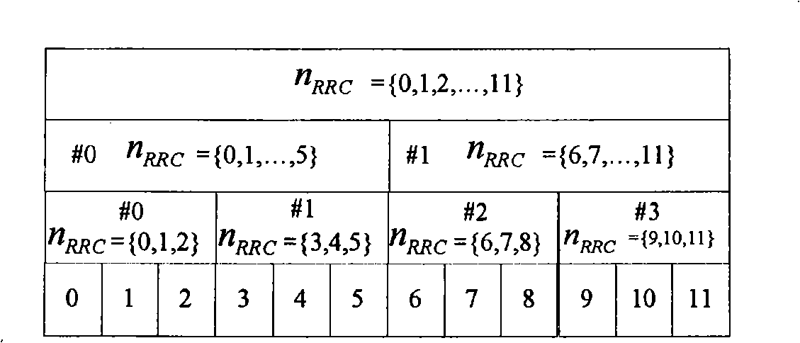
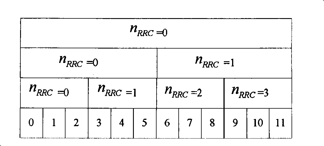
[0089] In this embodiment, the base station allocates resources for the SRS signal, which corresponds to a node in the tree structure in the frequency domain, and configures the SRS bandwidth parameter B according to the layer where the node is located. SRS , according to which node is in the SRS The index in the determined layer configures the SRS frequency domain position parameter n RRC (The index of the nodes in each layer starts from 0 and is numbered sequentially by 0, 1, 2, 3...), so n RRC The value range of is:

[0090] n RRC = { 0,1 , . . . , ( Π b ...

example 1

[0102] like Figure 4 As shown, for configuration 0 in Table 2, if the base station adopts the method of the first embodiment, the UE-specific parameter configuration is B SRS = 1, n RRC= 6, the corresponding frequency domain resource is Figure 4 B SRS = 1 in the corresponding layer Indicates the area, where n RRC Can be any of {6, 7, 8, 9, 10, 11}.

[0103] After receiving the above parameters, the terminal obtains according to configuration 0 in Table 2:

[0104] N 0 =1,N 1 = 2,N 2 = 2,N 3 =3

[0105] m SRS,0 =48, m SRS,1 =24,m SRS,2 =12,m SRS,3 =4

[0106] m SRS , B SRS = m SRS , 1 = 24

[0107] according to b=0, 1, . . . , B SRS Calculated to get:

[0108]

[0109]

[0110] If the base station adopts the method of ...


PUM


Abstract

The invention relates to a transmission method of uplink channel measuring reference signals. A base station allocates resources to the uplink channel measuring reference signal of a terminal, namely an SRS signal and sends SRS configuration parameters to the terminal, including an SRS bandwidth parameter BSRS and an SRS frequency domain position parameters; after the SRS configuration parameters are received by the terminal, the parameters of resources for sending SRS signals are calculated, including frequency domain initial position of the SRS signal, and then the SRS signal is sent to the base station by using the resources; wherein, the base station is a node in a tree structure of SRS bandwidth configuration corresponding to the frequency domain resource distributed by the SRS signal, the BSRS configured is corresponding to a layer where the node is positioned, NRRC configured is corresponding to an index of a branch node when the node is positioned at the lowest layer of the tree structure or is corresponding to an index in a layer determined by the BSRS when the node is positioned in the tree structure. The transmission method ensures that the base station can accurately measure uplink and downlink channels.

Description

technical field [0001] The invention relates to the field of mobile wireless communication, in particular to a transmission method of an uplink channel measurement reference signal in a wireless communication system. Background technique [0002] In the LTE (Long Term Evolution, long-term evolution) system, the uplink channel measurement reference signal (Sounding Reference Signal) is a signal sent by the UE (User Equipment, user equipment, also referred to as a terminal in this text) to the base station, and is mainly used for base station measurement For the quality of the uplink channel, the base station completes the scheduling of uplink data according to the measurement results, such as the frequency resource occupied during uplink transmission, or the modulation and coding method used, etc. [0003] In the current LTE system, multiple SRS bandwidths are supported. The SRS bandwidth is configured in a tree structure, and each SRS bandwidth configuration (ie, SRS bandwi...

Claims


Application Information

Patent Timeline
Patent Type & Authority Applications(China)
IPC IPC(8): H04B7/26H04Q7/38
CPCH04L5/0007H04L5/0048H04L5/0051H04L5/0094H04L27/261H04W72/04H04W72/23
Inventor 梁春丽郝鹏夏树强戴博
Owner ZTE CORP
Why Eureka
Try Eureka