Method of transmitting scheduling requests over uplink channels

a scheduling request and uplink channel technology, applied in the field of communication systems, can solve the problems of inability the inability of the base station to transmit scheduled data and unscheduled scheduling requests concurrently on scheduled and unscheduled channels, and the inability of the base station to predict the actual arrival of the mobile uni

Inactive Publication Date: 2008-12-25
LUCENT TECH INC
View PDF7 Cites 111 Cited by
  • Summary
  • Abstract
  • Description
  • Claims
  • Application Information

AI Technical Summary

Benefits of technology

[0013]The present invention is directed to addressing the effects of one or more of the problems set forth above. The following presents a simplified summary of the invention in order to provide a basic understanding of some aspects of the invention. This summary is not an exhaustive overview of the invention. It is not intended to identify key or critical elements of the invention or to delineate the scope of the invention. Its sole purpose is to present some concepts in a simplified form as a prelude to the more detailed description that is discussed later.
[0014]In various embodiments of the present invention, methods are provided for transmitting scheduling requests over uplink channels. One embodiment includes determining whether a first resource for transmission of a scheduling request over an unscheduled uplink co...

Problems solved by technology

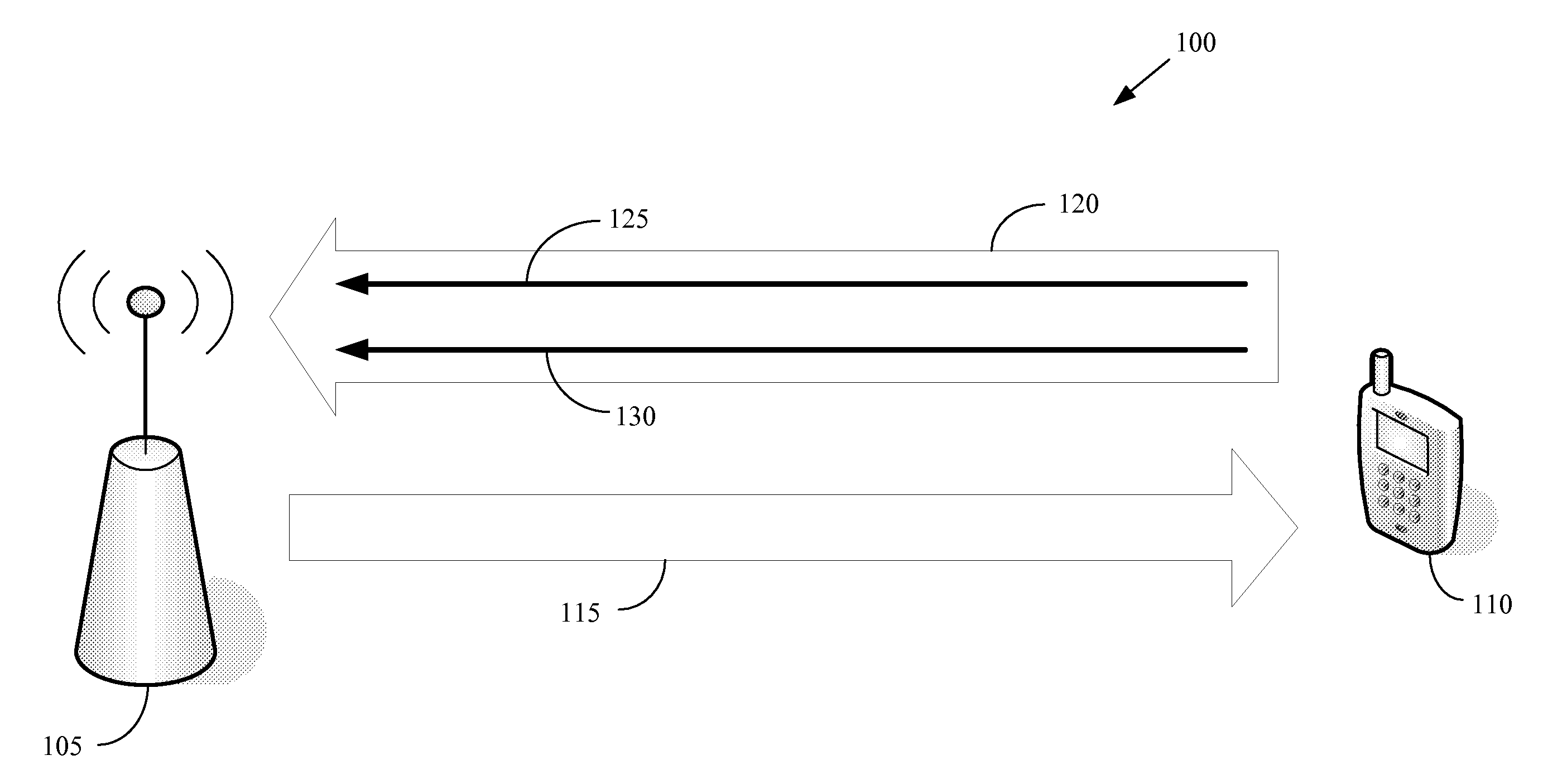
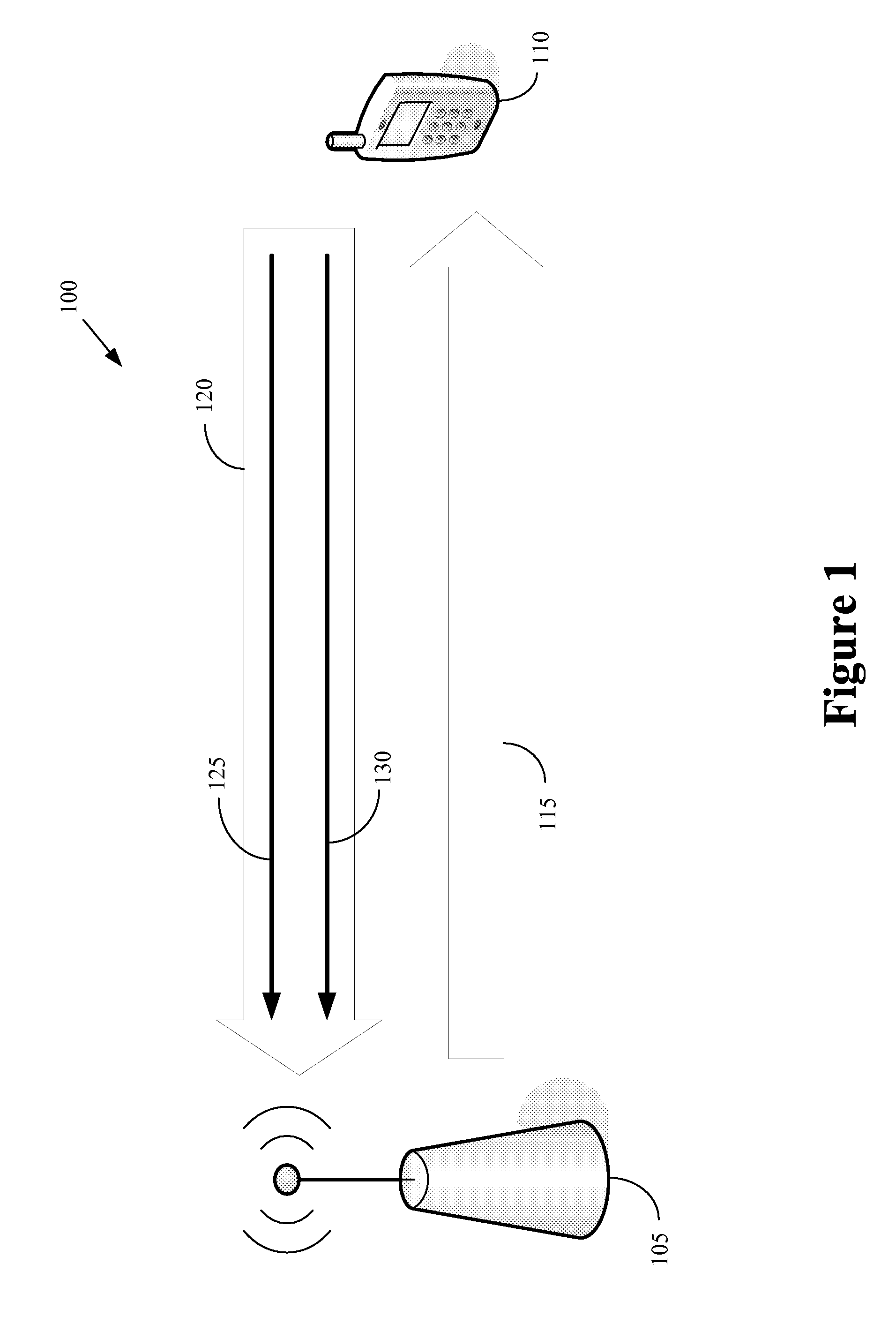
However, due to constraints on the peak-to-average power of the transmitter, the UMTS-LTE standards specify that information cannot be transmitted concurrently on the scheduled and unscheduled channels by the same mobile unit.
Thus, the base station cannot predict when the mobile unit will actually transmit a scheduling request.
The base station cannot predict when the scheduled data and unscheduled scheduling request will collide.
Consequently, the base station cannot predict when the m...

Method used


Image

  • Method of transmitting scheduling requests over uplink channels
  • Method of transmitting scheduling requests over uplink channels
  • Method of transmitting scheduling requests over uplink channels

Examples


Embodiment Construction

[0021]Illustrative embodiments of the invention are described below. In the interest of clarity, not all features of an actual implementation are described in this specification. It will of course be appreciated that in the development of any such actual embodiment, numerous implementation-specific decisions should be made to achieve the developers' specific goals, such as compliance with system-related and business-related constraints, which will vary from one implementation to another. Moreover, it will be appreciated that such a development effort might be complex and time-consuming, but would nevertheless be a routine undertaking for those of ordinary skill in the art having the benefit of this disclosure.

[0022]Portions of the present invention and corresponding detailed description are presented in terms of software, or algorithms and symbolic representations of operations on data bits within a computer memory. These descriptions and representations are the ones by which those ...


PUM


Abstract

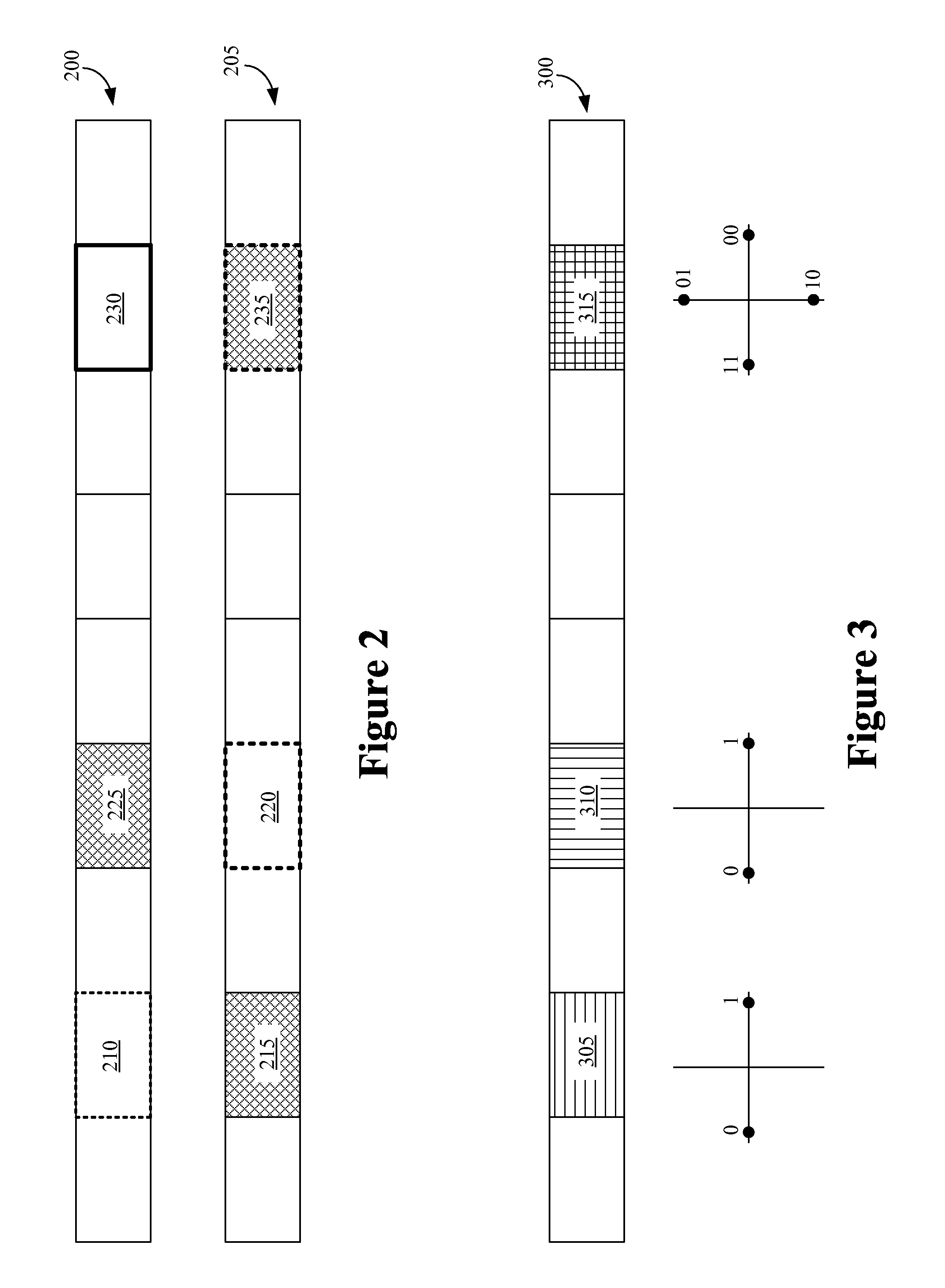
In various embodiments of the present invention, methods are provided for transmitting scheduling requests over uplink channels. One embodiment includes determining whether a first resource for transmission of a scheduling request over an unscheduled uplink control channel is allocated concurrently with a second resource for transmission of user data over a scheduled uplink shared channel. This embodiment also includes encoding the user data and bit(s) of control information to form encoded information for transmission using the second resource. The additional bit(s) indicate whether the mobile unit is transmitting the scheduling request. Another embodiment includes determining whether a first resource for transmission of a scheduling request over an unscheduled uplink control channel is allocated concurrently with a second resource for transmission of other control information over the unscheduled uplink control channel. This embodiment includes modulating the scheduling request and the other control information into one symbol for transmission using the first resource.

Description

BACKGROUND OF THE INVENTION[0001]1. Field of the Invention[0002]This invention relates generally to communication systems, and, more particularly, to wireless communication systems.[0003]2. Description of the Related Art[0004]The coverage area of a wireless communication system is typically divided into a number of cells or sectors, which may be grouped into one or more networks. Base stations provide wireless connectivity to the cells or sectors within the wireless communication system. Alternatively, wireless connectivity may be provided by access points, base station routers, access networks, and the like. Mobile units located in each cell may access the wireless communications system by establishing a wireless communication link, often referred to as an air interface, with the base station associated with the cell or sector. The mobile units may also be referred to using terms such as access terminal, user equipment, subscriber station, and the like. The mobile units may include...

Claims


Application Information

Patent Timeline
IPC IPC(8): H04Q7/20H04W28/06H04W74/00
CPCH04L1/0009H04L1/0026H04L1/1671H04W28/06H04W72/1284H04W72/21
Inventor BACHL, RAINERSCHNEIDER, MATTHIASLEE, JUNG A.
Owner LUCENT TECH INC
Why Eureka
Try Eureka