Pipeline for the hydraulic or pneumatic transport of solids

A technology for pipes and solids, applied in the field of pipes used for hydraulic or pneumatic conveying of solids, can solve the problems of wear and large deviation of the wall thickness of the wear ring, and achieve the effect of long life.

Inactive Publication Date: 2008-12-24
ESSER WERKE
View PDF2 Cites 7 Cited by
  • Summary
  • Abstract
  • Description
  • Claims
  • Application Information

AI Technical Summary

Problems solved by technology

This ultimately leads to greater deviations in the wall thickness of the wear ring in the transition region from one bend to the following bend or pipe piece and then to an even greater wear.

Method used


Image

  • Pipeline for the hydraulic or pneumatic transport of solids
  • Pipeline for the hydraulic or pneumatic transport of solids
  • Pipeline for the hydraulic or pneumatic transport of solids

Examples


Embodiment Construction

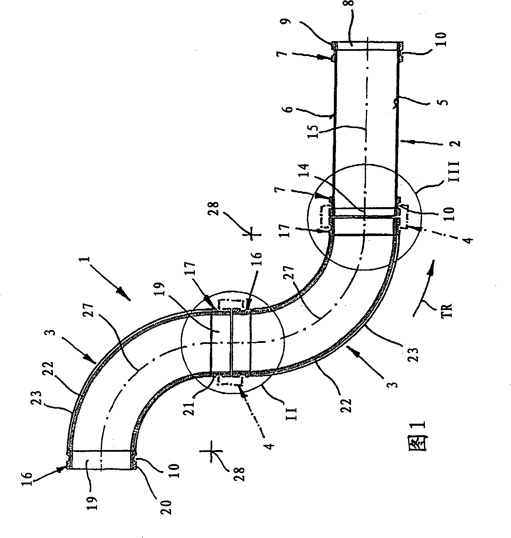
[0027] In FIG. 1 , a longitudinal section of a pipeline for hydraulically or pneumatically conveying solids, such as concrete, is designated by 1 . Such a pipe 1 finds practical use, for example in connection with a truck-mounted concrete pump, as a concrete distribution boom which can be turned over together. The pipeline 1 has a predetermined conveying direction, which is indicated by the arrow TR.

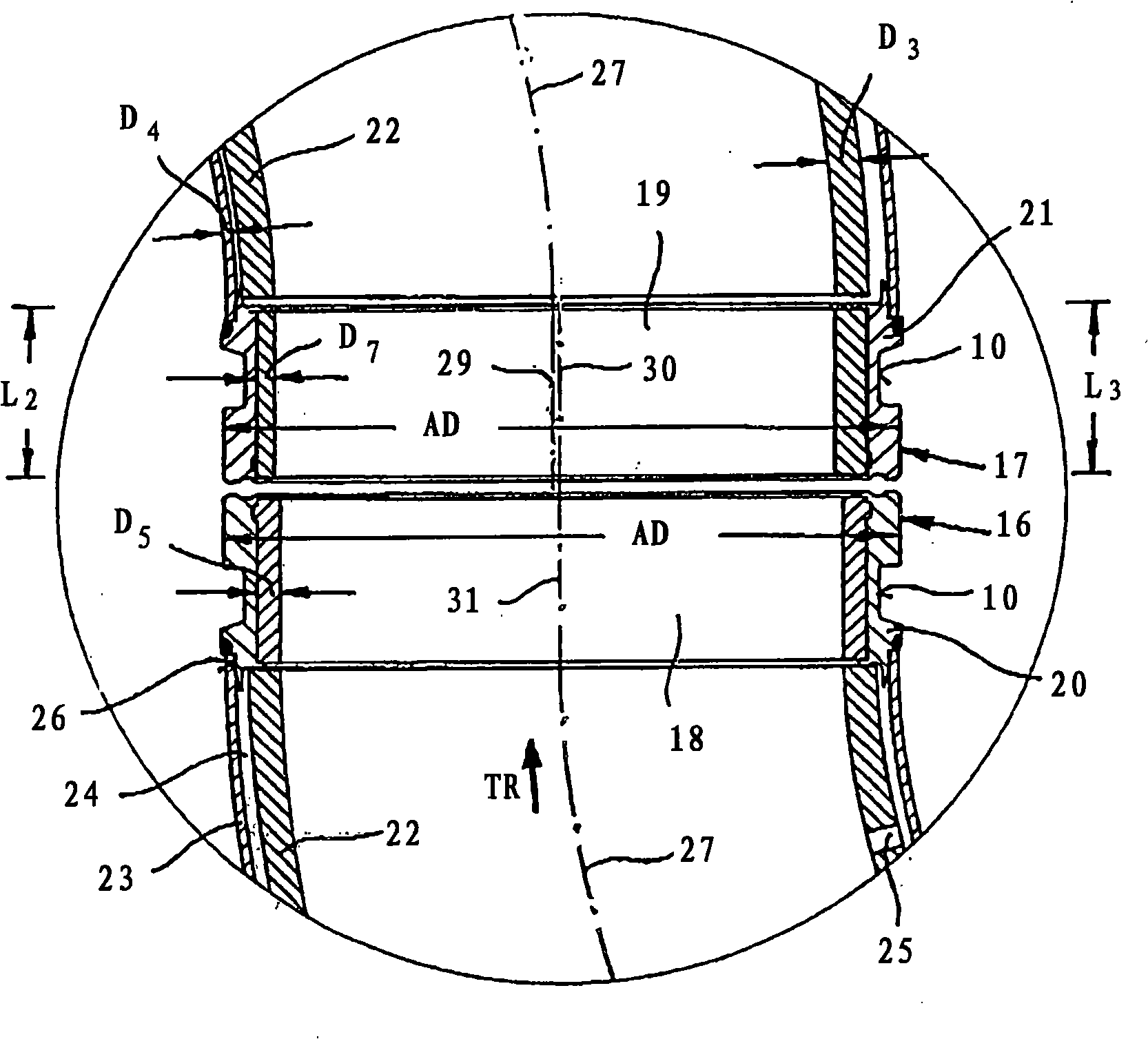
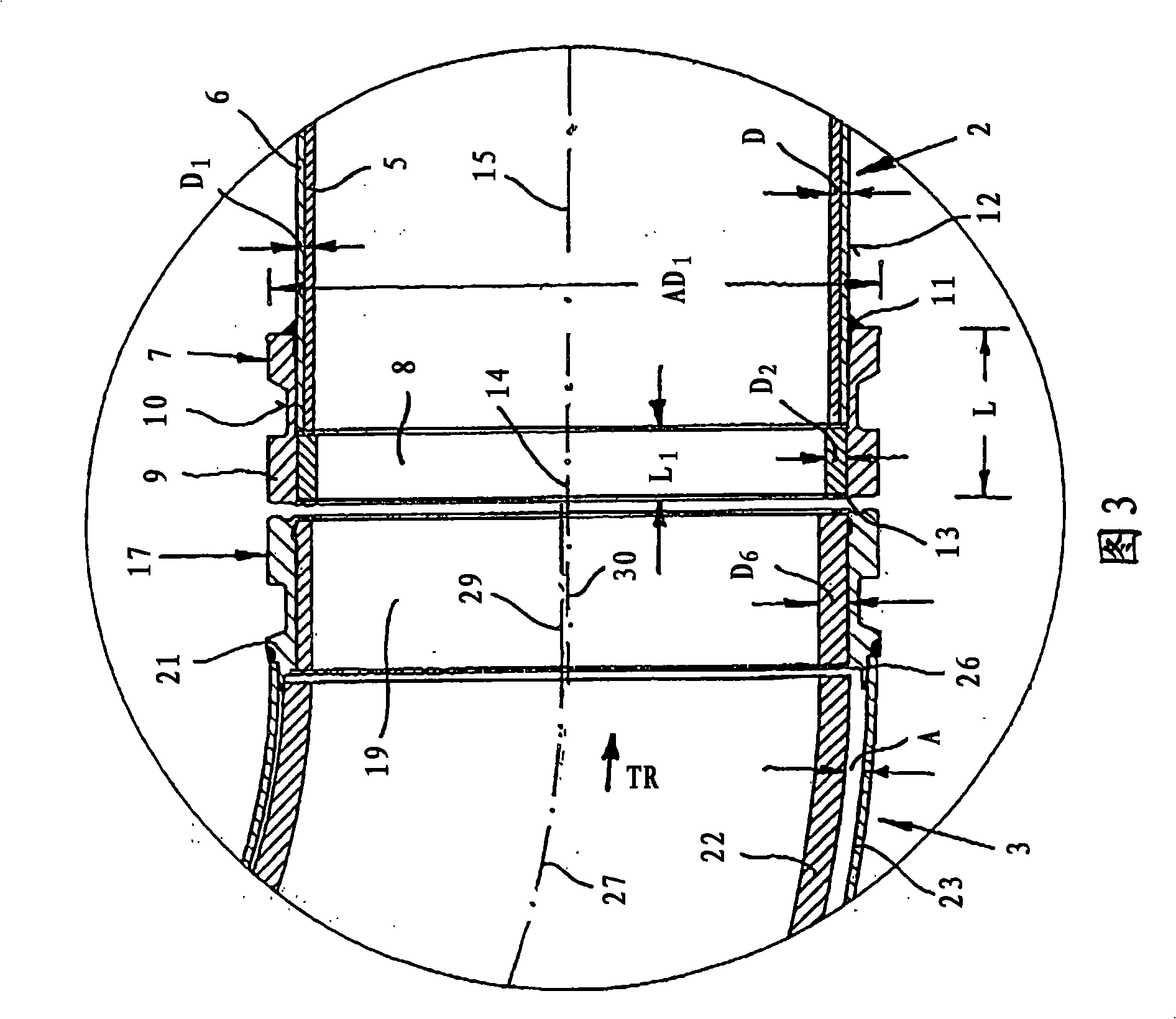
[0028] A pipe 1 with a length of up to more than 60 meters consists of a straight pipe piece 2 and an elbow 3 with a 90° bend, the contour of which allows two elbows 3 following each other, or one elbow 3 And a pipe 2 which is not only connected by means of a shell coupling 4 which is only schematically depicted, but which also allows relative rotation of the pipe 2 and the elbow 3 within the shell coupling 4 . The long pipe 1 is folded in such a way that it can be moved from one installation position to another on a movable pipe base.

[0029] The pipe part 2 (see FIGS. 1 and...


PUM


Abstract

A piping (1) comprises straight pipe sections (2) and curved pipe bends (3) having each an inner pipe (5; 22), an outer pipe (6; 23) and end, double-layered coupling flanges (7; 16, 17) composed of inner wear rings (8; 18, 19) and outer annular collars (9; 20, 21) with coupling grooves (10). Pipe sections (2) and / or pipe bends (3) which follow one another in sections are detachably coupled by split couplings (4) that act as revolute joints and pipe connectors. The wear rings (19) in the coupling flanges (17) of the pipe bends (3) at the outlet end of the piping have different wall thicknesses about their circumferences, while the wear rings (18) in the coupling flanges (16) at the inlet end of the piping and in the coupling flanges (7) of the pipe sections (2) have a uniform wall thickness about their circumference.; The wall thickness of the wear rings (19) in the coupling flanges (17) of the pipe bends (3) at the outlet end of the piping is greater in the circumferential sections further away from the curvature mid-points (28) of the pipe bends (3) than in the circumferential sections closer to the curvature mid-points (28).

Description

technical field [0001] The invention relates to a line for hydraulically or pneumatically transporting solids according to the features stated in the preamble of claim 1 . Background technique [0002] Pipelines of this type find widespread use especially as concrete placing booms in conjunction with truck-mounted concrete pumps. Basic criteria for such a pipe are its height of action, its distance of action, the form of folding and especially the number of swivel arms. [0003] Practical experience has shown that in the case of a standardized internal delivery cross-section of the connecting flange and thus also predetermined external contours and dimensions, especially with regard to the annular shoulder and the connecting groove, the same type of elbow connection method The wear volume of the wear ring integrated in the flange cannot be kept sufficiently large for all solids to be conveyed or conveyed in order to also prevent the straight pipe piece next to the bend from...

Claims


Application Information

Patent Timeline
IPC IPC(8): B65G53/52F16L43/00F16L57/06
CPCB65G53/523F16L43/001F16L57/06E04G21/0418B65G53/52F16L43/00
Inventor A·埃塞尔
Owner ESSER WERKE
Why Eureka
Try Eureka