Memory with retargetable memory cell redundancy

A technology of memory cells and memory arrays, used in static memory, instruments, etc., to solve problems such as programming time constraints

Inactive Publication Date: 2008-12-24
SANDISK TECH LLC
View PDF20 Cites 50 Cited by
  • Summary
  • Abstract
  • Description
  • Claims
  • Application Information

AI Technical Summary

Problems solved by technology

Also, since more cells in a large page are programmed together, programming time tends to be limited by the few slow cells that are not replaced

Method used


Image

  • Memory with retargetable memory cell redundancy
  • Memory with retargetable memory cell redundancy
  • Memory with retargetable memory cell redundancy

Examples


Embodiment Construction

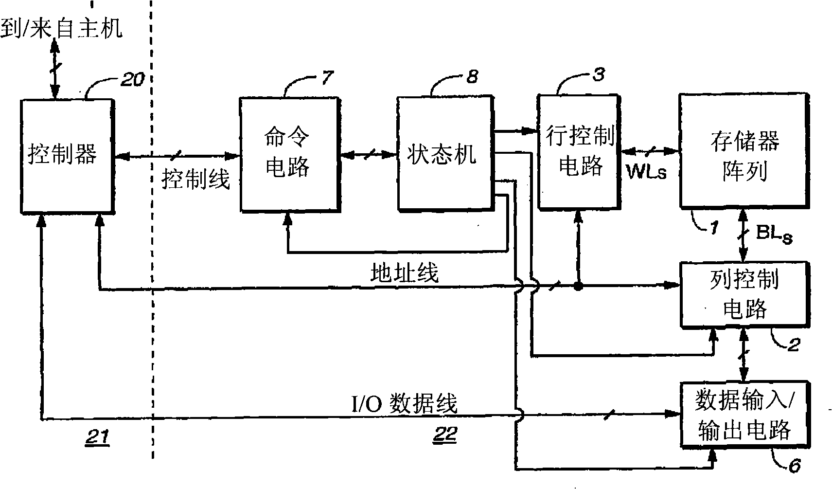
[0036] image 3 A memory system 330 is shown incorporating aspects of the invention. Memory system 330 is connected to and communicates with a host (not shown). This communication between the host and the memory system is typically performed through a standard interface. In some instances, a memory system (eg, memory system 330 ) is part of a removable memory card with a standard interface, so it can be connected to a wide variety of hosts according to standards such as those previously described. In an alternative arrangement, a memory system (eg, memory system 330 ) may be embedded in the host system, so it may be permanently connected to the host system.

[0037] The memory system 330 includes a controller 20 that controls the operation of the memory array 1 in response to commands received from the host. Controller 20 may contain a microprocessor, RAM, flash, buffers, registers, error correction code (ECC) circuits, and other circuits for managing memory system 330 . Wh...


PUM


Abstract

In a memory array having redundant columns, a scheme allows defective cells to be individually remapped to redundant cells in a redundant column. Redundant cells in one redundant column replace defective cells in multiple non-redundant columns. Remapping is done as part of initial test and configuration. Specific hardware can be used for the scheme or firmware in the memory controller can implement the scheme.

Description

technical field [0001] The present invention relates to non-volatile memory, and in particular to using redundant data storage cells in flash memory to replace defective data storage cells. Background technique [0002] There are many commercially successful non-volatile memory products in use today, especially in the form of small form factor cards, which employ flash EEPROM (Electrically Erasable Programmable Read-Only memory) array of cells. A memory controller, usually but not necessarily on a separate integrated circuit chip, interfaces with a host to which the card is removably connected and controls the operation of the on-card memory array. This controller usually consists of a microprocessor, some nonvolatile read-only memory (ROM), volatile random-access memory (RAM), and one or more special circuits, such as Special circuitry that calculates an Error Correction Code (ECC) from the data as it passes through the controller. Some of the commercially available card...

Claims


Application Information

Patent Timeline
Patent Type & Authority Applications(China)
IPC IPC(8): G11C29/00
Inventor 凯文·M·康利约拉姆·锡达
Owner SANDISK TECH LLC
Why Eureka
Try Eureka