Mixer circuit and method

A technology of mixers and quadrature mixers, applied to electrical components, networks with variable switching times, transmission systems, etc., can solve problems that hinder the convenient integration of transceiver circuits

Active Publication Date: 2008-12-24
TELEFON AB LM ERICSSON (PUBL)
View PDF0 Cites 15 Cited by
  • Summary
  • Abstract
  • Description
  • Claims
  • Application Information

AI Technical Summary

Benefits of technology

The technical effect of this patented technology lies within its own unique characteristics that make it useful for different purposes or applications.

Problems solved by technology

The technical problem addressed in this patents relating to communication receivers used for FDD systems involves achieving better reception while reducing unwanted signals due to strong electrical coupling through nearby transmitted components such as antennas. This can lead to reduced data transfer rates and increased power consumption during operation. To address this issue, certain techniques have been developed involving placing an anti-reflection coil near each component within the receiver itself. These methods aimed towards improving filtering efficiency without adding extra hardware elements like SAW filters.

Method used


Image

  • Mixer circuit and method
  • Mixer circuit and method
  • Mixer circuit and method

Examples


Embodiment Construction

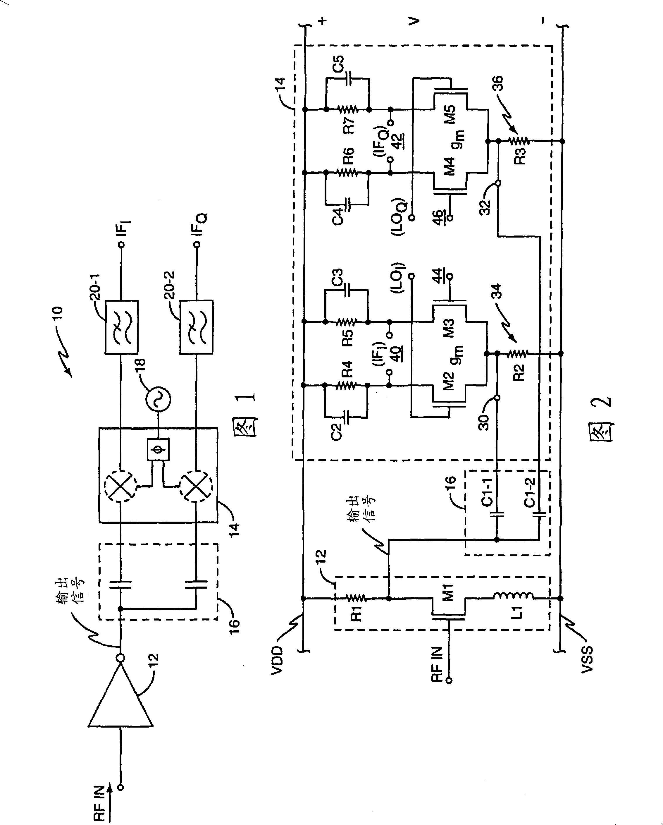
[0022] FIG. 1 partially shows a wireless communication receiver, such as used in a cellular radiotelephone or other wireless communication device, wherein the receiver circuit 10 includes a low noise amplifier circuit 12, a mixer circuit 14 and a coupling circuit implemented here as a capacitive coupling circuit. circuit 16. FIG. 1 also shows local oscillator circuit 18, which provides a local oscillator (LO) signal to mixer circuit 14 to downconvert the output signal of low noise amplifier circuit 12 from the received RF frequency. is an intermediate frequency (IF) signal, which may be filtered by filter circuits 20-1 and 20-2. Although these filter circuits are depicted as outputting filtered IF I and IF Q signal, but the mixer circuit 14 is not limited to a quadrature configuration, nor is it limited to IF conversion.

[0023] In operation, low noise amplifier circuit 12 generates its output signal in response to an RF input signal, such as a filtered, antenna-received r...


PUM


Abstract

A method of providing an input signal to a mixer circuit comprises coupling an output signal from a low-noise amplifier circuit to a mixer input of the mixer circuit via an AC coupling circuit, comprising an inductive of capacitive coupling circuit. For capacitive coupling configurations, a coupling capacitor is configured to have a capacitance value determined as a function of a transconductance sensitivity of the mixer circuit. For balanced output configurations of the low-noise amplifier circuit, matched coupling capacitors are used for coupling the balanced output signals to respective inputs of the mixer circuit. In one embodiment, the mixer circuit comprises a quadrature mixer circuit, which may be in a balanced or double-balanced configuration. In another embodiment, the mixer circuit comprises a four-phase mixer circuit, which may be configured as a balanced four-phase mixer circuit coupled to the low-noise amplifier circuit via inductive or capactive embodiments of the coupling circuit.

Description


Claims


Application Information

Patent Timeline
Owner TELEFON AB LM ERICSSON (PUBL)
Why Eureka
Try Eureka