Mini water pump

A technology of miniature water pumps and water levels, applied to pumps, pump devices, pump components, etc., can solve the problems of shortening the service life of water pumps, and achieve the effects of reduced power consumption, long service life and low noise

Inactive Publication Date: 2008-12-31
杭州华宁电器有限公司
View PDF1 Cites 8 Cited by
  • Summary
  • Abstract
  • Description
  • Claims
  • Application Information

AI Technical Summary

Problems solved by technology

The water pump adopts the sealing ring structure and is assembled from multiple parts. The friction between the parts will generate noise and shorten the service life of the water pump.

Method used


Image

  • Mini water pump
  • Mini water pump
  • Mini water pump

Examples


Embodiment Construction

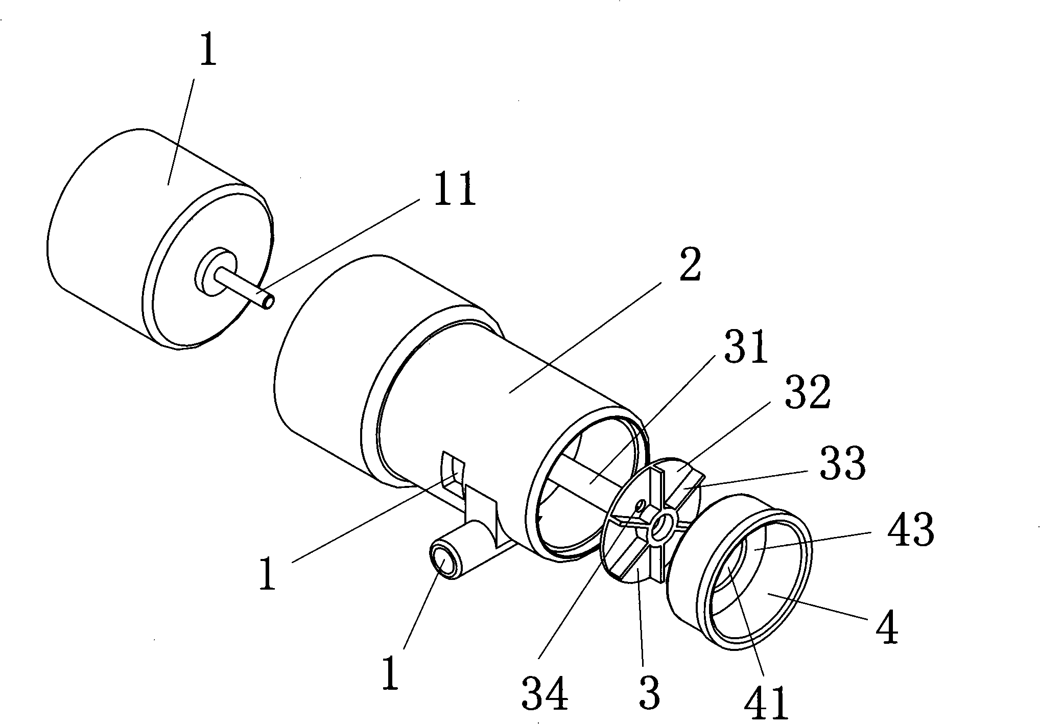
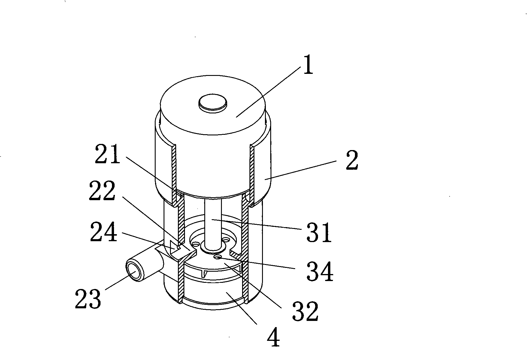
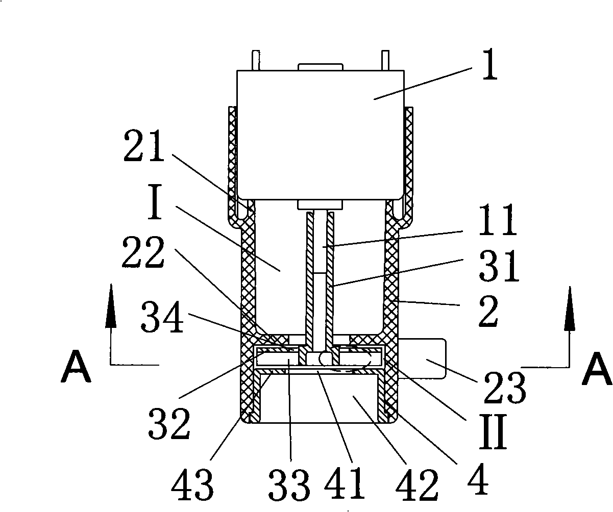
[0016] see Figure 1 ~ Figure 4 , this embodiment includes a motor 1, a housing 2, an impeller 3 and an end cover 4, the inner wall of the housing 2 is provided with an outwardly protruding flange 21 and a boss 22, and the outer wall of the housing 2 is provided with an outlet along its tangential direction. The water outlet 23 has a water level hole 24 parallel to the end surface of the housing 2 on the circumferential wall of the housing 2, the water level hole 24 is located above the water outlet 23, and the lower edge of the water level hole 24 is flush with the upper edge of the boss 22 , that is, the lower edge of the water level hole 24 and the upper edge of the boss 22 are on the same plane. The impeller 3 is composed of an integrated impeller shaft 31, a chassis 32 and six blades 33, the impeller shaft 31 is located above the chassis 32, and the six blades 33 are uniformly distributed under the chassis 32 in a radial form centered on the center of the chassis 32 , th...


PUM


Abstract

The invention discloses a micro water pump, which comprises a motor, a casing body, an impeller and an end cover. Outward convex flange and dummy club are arranged on an inner wall of the casing body, a water outlet opening is arranged on the outer wall of the casing body along the tangent direction, a water level hole parallel to the end surface of the casing body and positioned above the water outlet opening is arranged on the circumferential wall of the casing body, and the lower edge of the water level hole is flush with the upper edge of the dummy club; the impeller is composed of an impeller shaft, a chassis and a plurality of blades of an integral structure, the impeller shaft is positioned above the chassis, the blades are uniformly distributed below the chassis, and a plurality of air vents are arranged on the chassis; a cavity is arranged in the end cover, and a central hole is arranged on the end surface of the water pump; the motor, the impeller and the end cover are arranged in the cavity, wherein, a motor shaft is positioned in the impeller shaft and is tightly fitted, the chassis and the blades of the impeller are positioned between the dummy club of the casing body and the end surface of the end cover, and the impeller, the casing body and the end cover are not contacted; the cavities formed among the water outlet opening, the dummy club and the end cover are communicated. The invention has the advantages that the structure is simple, the sealing element is not required, the service life is long, and the noise is low.

Description

technical field [0001] The invention relates to a water pump, in particular to a centrifugal micro water pump. Background technique [0002] In order to prevent water from leaking from between the impeller shaft or motor shaft and the water pump cavity in the existing micro-water pump, so that the motor enters water, a sealing ring needs to be provided between the impeller shaft or motor shaft and the water pump housing, or Installing the motor in a sealed cavity not only has many components, but also has a complex structure. [0003] For example, the "micro-water pump" disclosed in Chinese utility model patent 02272679.9 includes a micro-motor, a pump base, a pump cover, an impeller and a sealing ring. The pump base is fixed on the motor casing by screws, and the active magnetic ring is fixed on the motor shaft. A shaft frame is placed between the shaft frame and the pump cover, and a sealing ring is placed between the shaft frame and the pump cover. The pump seat and the ...

Claims


Application Information

Patent Timeline
Patent Type & Authority Applications(China)
IPC IPC(8): F04D13/06F04D29/42F04D29/24F04D29/70F04D29/00
Inventor 杨建忠沈丹华
Owner 杭州华宁电器有限公司
Why Eureka
Try Eureka