Clock
A clock and watch mirror technology, applied in the field of clocks and watches, can solve the problems of reduced durability of the watch case and insufficient receiving sensitivity, and achieve the effects of improving receiving sensitivity, good design, and avoiding the offset of buffer parts
- Summary
- Abstract
- Description
- Claims
- Application Information
AI Technical Summary
Problems solved by technology
Method used
Image

Examples
no. 1 approach
[0056] A radio-controlled timepiece according to a first embodiment of the present invention will be described below with reference to the drawings.
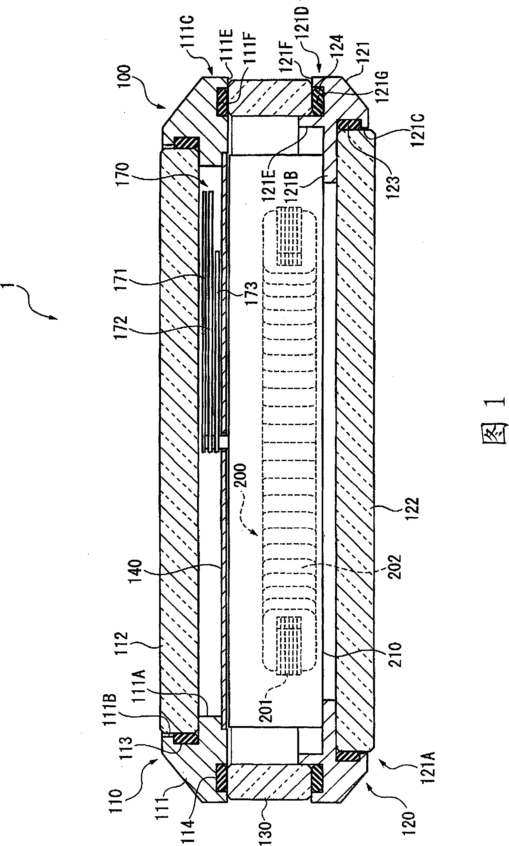
[0057] FIG. 1 is a side sectional view showing an outline of a radio-controlled timepiece according to a first embodiment of the present invention.
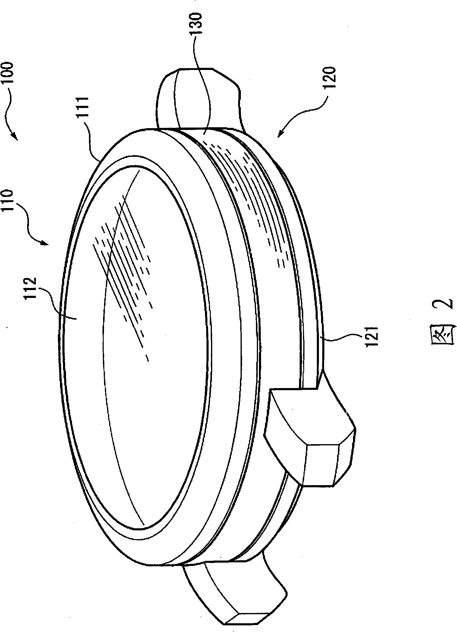
[0058] FIG. 2 is a perspective view schematically showing a case of the radio-controlled timepiece of the above-mentioned embodiment.
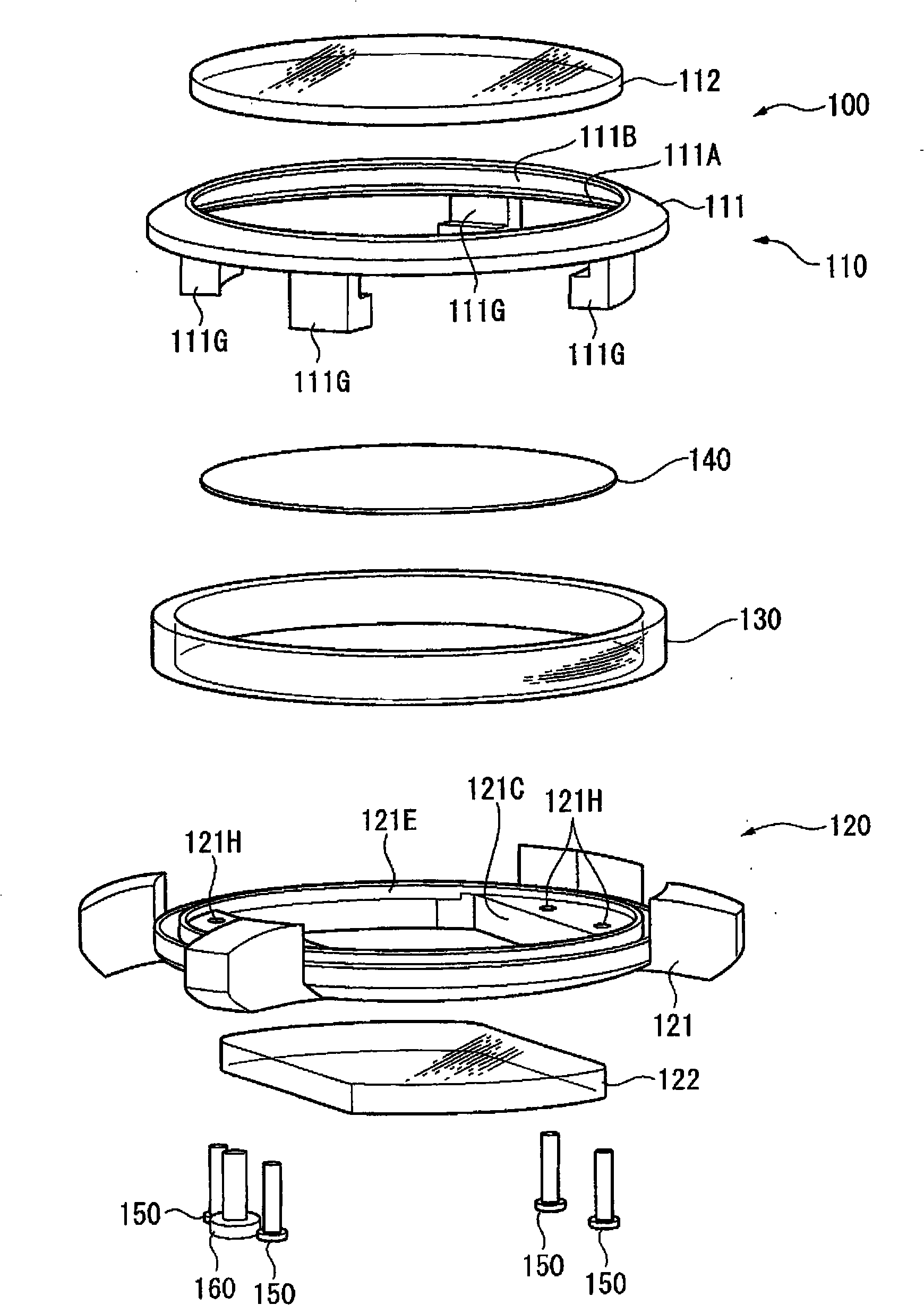
[0059] image 3 It is an exploded perspective view of the case of the radio-controlled timepiece of the above-mentioned embodiment.
[0060] Figure 4 It is an enlarged cross-sectional view of a part of the periphery of the case of the radio-controlled timepiece of the above-mentioned embodiment.
[0061] Figure 5 It is a cross-sectional view showing the fixing structure of the peripheral portion of the case of the radio-controlled timepiece of the above-mentioned embodiment.
[0062] As shown in FIG. 1 , the radio controlled timepiece 1 of th...
no. 2 approach
[0117] Next, a radio controlled timepiece according to a second embodiment of the present invention will be described with reference to the drawings.
[0118] Fig. 6 is a side sectional view showing an outline of a timepiece according to a second embodiment of the present invention.
[0119] FIG. 7 is a perspective view schematically showing a case of the timepiece according to the second embodiment.
[0120] Figure 8 It is an exploded perspective view of the case of the timepiece of the said 2nd Embodiment.
[0121] Figure 9 It is an enlarged cross-sectional view of a part of the periphery of the case of the timepiece of the second embodiment.
[0122] Figure 10 It is a cross-sectional view showing the fixing structure of the peripheral portion of the case of the timepiece according to the second embodiment.
[0123] (Composition of clock)
[0124] As shown in FIG. 6 , the timepiece 1A of the second embodiment has a case 100 and a movement 210 as a timepiece body.
...
PUM
 Abstract
Description
Claims
Application Information
 - R&D
- Intellectual Property
- Life Sciences
- Materials
- Tech Scout
- Unparalleled Data Quality
- Higher Quality Content
- 60% Fewer Hallucinations
Browse by: Latest US Patents, China's latest patents, Technical Efficacy Thesaurus, Application Domain, Technology Topic, Popular Technical Reports.
© 2025 PatSnap. All rights reserved.Legal|Privacy policy|Modern Slavery Act Transparency Statement|Sitemap|About US| Contact US: help@patsnap.com