Supercharge Your Innovation With Domain-Expert AI Agents!

Band pass filter

A band-pass filter and inductor technology, applied in impedance networks, electrical components, single-ended-pair networks, etc., can solve the problems of poor passband response, increase circuit layout space, etc., and achieve the effect of accelerating the band gap attenuation rate.

Active Publication Date: 2008-12-31
ADVANCED SEMICON ENG INC
View PDF0 Cites 10 Cited by
  • Summary
  • Abstract
  • Description
  • Claims
  • Application Information

AI Technical Summary

Problems solved by technology

However, these resonant circuits usually degrade the passband response and increase the layout space required

Method used


Image

  • Band pass filter
  • Band pass filter
  • Band pass filter

Examples


Embodiment Construction

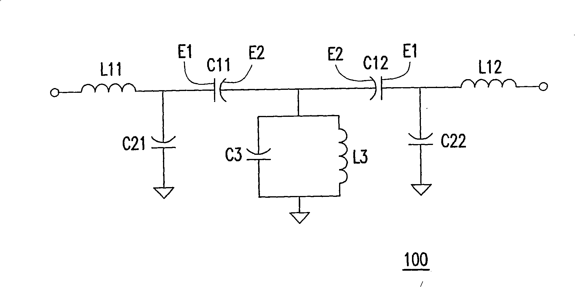
[0049] figure 1 A prototype circuit of the bandpass filter of the present invention is shown. Please refer to figure 1 , the bandpass filter 100 includes a plurality of passive elements electrically connected in a specific relationship. The bandpass filter 100 includes a first series inductor L11, a first series capacitor C11, a second series capacitor C12 and a second series inductor L12. One end of the first series capacitor C11 is electrically connected to one end of the first series inductor L11, and one end of the second series capacitor C12 is electrically connected to the other end of the first series capacitor C11, and one end of the second series inductor L12 is electrically connected to the second series inductor L12. The other end of the second string capacitor C12.

[0050] In addition, the bandpass filter 100 further includes a first capacitor C21 and a second capacitor C22. One end of the first capacitor C21 is electrically connected to the other end of the f...


PUM


Abstract

The invention discloses a band-pass filter which comprises a prototype circuit. In the prototype circuit, at least two of multiple components interact for producing at least one mutual capacitance or at least one mutual inductance which forms a resonance circuit with the prototype circuit for creating at least one transmission zero used for speeding up forbidden band attenuation rate.

Description

technical field [0001] The present invention relates to a band-pass filter. Background technique [0002] With the advancement of technology, wireless communication systems such as mobile phones, Bluetooth (Bluetooth), home cordless phones (CordlessPhone), and wireless local area networks (Wireless Local Area Network, WLAN) are increasingly popular. A bandpass filter is often configured in a wireless communication system, and its main function is to allow passband signals to pass through and filter out other interference signals outside the passband. In order to obtain a better filtering effect, the resonance circuit can be used to increase the transmission zero of the bandpass filter to increase the attenuation rate of the forbidden band (ie, the frequency band other than the passband). However, these resonant circuits usually degrade the passband response and increase the layout space required. Contents of the invention [0003] In view of this, the main purpose of the...

Claims


Application Information

Patent Timeline
IPC IPC(8): H03H5/12
Inventor 李宝男邱基综
Owner ADVANCED SEMICON ENG INC
Features
  • R&D
  • Intellectual Property
  • Life Sciences
  • Materials
  • Tech Scout
  • Unparalleled Data Quality
  • Higher Quality Content
  • 60% Fewer Hallucinations
Learn More