
Active magnetic refrigerator

A magnetic refrigerator, active technology, applied in refrigerators, refrigeration and liquefaction, machines using electric/magnetic effects, etc., can solve the problems of heat exchange efficiency decline, loss, and inability to control the amount of heat transfer fluid, etc., to achieve installation Simplification, improvement of heat exchange efficiency, and excellent layout effect

Inactive Publication Date: 2008-12-31
DAEWOO ELECTRONICS CO LTD
View PDF2 Cites 24 Cited by
  • Summary
  • Abstract
  • Description
  • Claims
  • Application Information

AI Technical Summary

Problems solved by technology

However, the high-temperature heat transfer fluid that has not passed through the hot side heat exchanger 70 is reversely circulated through the channel switch 30 to return to the AMR bed 10
Therefore, it is difficult to achieve the cooling effect
[0006] like image 3 As shown, since the magnetic heat exchange unit 10 includes the inlet 18a and the outlet 18b of the heat transfer fluid, when the channel switch 30 operates, the high temperature heat transfer fluid in the magnetic heat exchange unit cannot be used up due to the reverse circulation, so that the heat Decreased exchange efficiency
[0007] In addition, since the conventional active magnetic refrigerator uses a single heat transfer fluid, the amount of the heat transfer fluid passing through the hot side cannot be controlled, so that the heat of the magnetocaloric material 16 cannot be rapidly cooled, resulting in a decrease in heat exchange efficiency
[0008] In addition, since the fine mesh 16 is used at the outlet in order to prevent the loss of the powdery magnetocaloric material 16 due to the heat transfer fluid (coolant), this causes the coolant to not circulate smoothly.
[0009] Also, since the coolant continues to pass through the magnetocaloric material 16 at the same location, it is difficult to achieve smooth heat exchange
[0010] In addition, the microscopic size of the magnetocaloric material 16 may be lost when the coolant enters and exits the magnetocaloric unit 10

Method used


Image

  • Active magnetic refrigerator
  • Active magnetic refrigerator
  • Active magnetic refrigerator

Examples


no. 1 approach

[0090] Image 6 is a configuration diagram showing a magnetic refrigerator according to a first preferred embodiment of the present invention. Figure 7 is for Image 6 The plan view of the magnet unit of the active magnetic refrigerator, while Figure 8 is for Image 6 Perspective view of the exterior of the magnetic heat exchange unit of the active magnetic refrigerator.

[0091] like Figure 6 to Figure 8 As shown, the active magnetic refrigerator according to this preferred embodiment of the present invention includes a first magnetic heat exchange unit 113A and a second magnetic heat exchange unit 113B with magnetocaloric materials, for supplying Two magnetic heat exchange units 113B, the magnet unit 140 applying a magnetic field or canceling their magnetic field, the hot heat exchanger 162, the cold heat exchanger 163, the first solenoid valve 120a and the second solenoid valve 120b.

[0092] The heat transfer fluid is divided into first heat transfer fluids 17aa an...

no. 2 approach

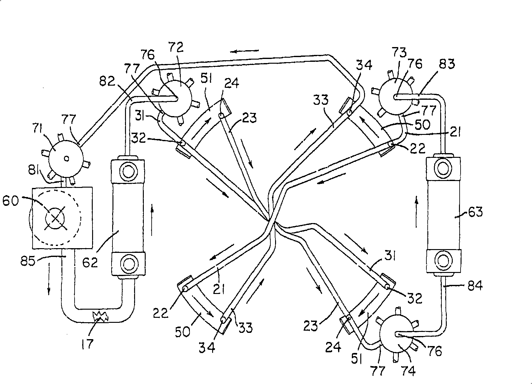
[0139] Figure 14 and Figure 15 is a plan view showing the circulation of the heat transfer fluid of the active magnetic refrigerator according to the second preferred embodiment of the present invention according to the position of the magnet, Figure 16 is shown simultaneously Figure 14 and Figure 15 The floor plan of the cycle, Figure 17 is a schematic diagram representing the rotating assembly of the magnet, while Figure 18 and Figure 19 It is a perspective view and a partially enlarged view of a guide table having a flow path.

[0140] like Figure 14 to Figure 19As shown, the active magnetic refrigerator according to this preferred embodiment of the present invention includes first magnetic heat exchange units 113A and 133A' and second magnetic heat exchange units 113B and 113B' containing magnetocaloric materials, accessories to the magnetic heat exchange units The magnet 1141 of 113A, 113A', 113B and 113B', the magnet rotating assembly 1140 for applying an...


PUM


Abstract

The invention relates to an active magnetic refrigerator includes separated hot and cold heat exchange units wherein a heat transfer fluid that exchanges a heat with a magnetic heat exchange unit having the magnetocaloric material pieces arranged to have a gap therebetween separately circulates through a solenoid valve.

Description

technical field [0001] The invention relates to an active magnetic refrigerator, which includes a separate heat exchange unit and a cold heat exchange unit. Background technique [0002] A conventional active magnetic refrigerator is disclosed in US Patent No. 6,826,915. like figure 1 As shown, (a) the temperature of the magnetic refrigeration material on which a magnetic field is applied increases from the dotted line to the solid line as the magnet moves to the right. (b) The temperature of the magnetic refrigeration material drops from the dotted line to the solid line as the heat transfer fluid on the cold side moves toward the hot side, and the heat transfer fluid is gradually heated to become hotter at the right Heat exchange to dissipate heat. (c) The temperature of the magnetic refrigeration material whose magnetic field has been eliminated further decreases from the dotted line to the solid line as the magnet moves to the left. (d) Due to the movement of the hea...

Claims


Application Information

Patent Timeline
IPC IPC(8): F25B21/00
CPCY02B30/00F25B21/00F25B2321/0022
Inventor 申承勋李东棺
Owner DAEWOO ELECTRONICS CO LTD
Features
  • Generate Ideas
  • Intellectual Property
  • Life Sciences
  • Materials
  • Tech Scout
  • Unparalleled Data Quality
  • Higher Quality Content
  • 60% Fewer Hallucinations
Learn More