Method and system for determining drilling fluids leakage and overflow

A technology of drilling fluid and leakage, which is applied in the directions of surveying, earthwork drilling and production, wellbore/well components, etc., and can solve problems such as the lack of public methods for determining leaky layers

Active Publication Date: 2009-01-07
北京豪仪测控工程有限公司
View PDF1 Cites 13 Cited by
  • Summary
  • Abstract
  • Description
  • Claims
  • Application Information

AI Technical Summary

Problems solved by technology

However, the method for determining the leaky layer is not disclosed in this application

Method used


Image

  • Method and system for determining drilling fluids leakage and overflow

Examples


Embodiment 1

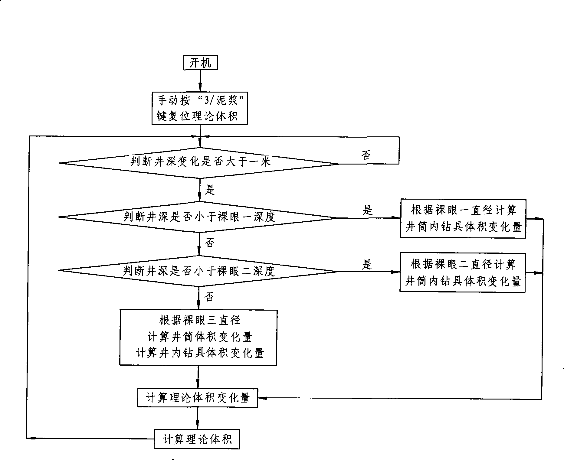
[0096] At a certain moment, manually press the "3 / overflow" button on the monitor host to reset the current well depth, and the well depth is 1301.10m at this time 3 , the pool volumes in the four mud tanks are measured by the ultrasonic liquid level sensor sensor installed in each mud tank respectively: 39.5m 3 , 42.6m 3 , 35.8m 3 , 38.5m 3 , that is, the total pool volume at this time is 156.4m 3 , assigning this value as the current theoretical volume 0 , namely: theoretical volume 0 =156.4m 3 .

[0097] It can be seen from the depth of the open hole that the well depth of 1301.10m is less than the depth of the open hole 2 of 2100m. According to the formula:

[0098] Wellbore volume = cross-sectional area of ​​open hole 1 × depth of open hole 1 + cross-sectional area of ​​open hole 2 × (well depth - depth of open hole 1)

[0099] The calculation results are as follows:

[0100] Wellbore volume = π × (0.4 / 2) 2 ×215+π×(0.35 / 2) 2 ×(1301.10-215)

[0101] =123.68m 3...

Embodiment 2

[0117] At a certain moment, manually press the "3 / overflow" button on the monitor host to reset the current well depth, and the well depth is 3452.20m at this time 3 , the pool volumes in the four mud tanks are: 41.1m 3 , 44.2m 3 , 37.4m 3 , 39.9m 3 , that is, the total pool volume at this time is 162.6m 3 , which is given as the current theoretical volume k , the theoretical volume k Equal to 162.6m 3 .

[0118] At this time, the well depth of 3452.20m is less than the depth of 4000m in the open hole 3, according to the formula:

[0119] Wellbore volume = cross-sectional area of ​​open hole 1 × depth of open hole 1 + cross-sectional area of ​​open hole 2 × depth of open hole 2 + cross-sectional area of ​​open hole 3 × (well depth - depth of open hole 2); the calculation results are as follows:

[0120] Wellbore volume = π × (0.4 / 2) 2 ×215+π×(0.35 / 2) 2 ×(2100-215)

[0121] +π×(0.25 / 2) 2 ×(3452.20-2100)

[0122] =251.28m 3

[0123] Drill volume = [π×(0.18 / 2) 2 -...


PUM


Abstract

The present invention relates to a method for measuring drill fluid spillage and a system adopting the method. The method calculates the difference value of the actual total pool cubage and the theoretic cubage to judge the real time state for boring a well. The method and the system have high automatization degree and high precision and can immediately confirm the spilling position and control effectively when drill fluid spillage occurs.

Description

【Technical field】 [0001] The present invention relates to a method of surveying a well or borehole, in particular to determine the location of a fluid spill in a well, and a system using the method. 【Background technique】 [0002] Lost circulation (or called lost circulation) is a common accident in oil and natural gas drilling engineering, and it is a trap where drilling fluid leaks into the formation during drilling. Lost circulation in drilling engineering will not only seriously affect construction safety, construction schedule and cost, but also seriously pollute oil and gas reservoirs and affect oil and gas products. The key to the plugging work is to determine the position of the lost zone as soon as possible after the lost circulation occurs, so as to take effective plugging measures in time to ensure the normal drilling. At present, the commonly used methods for determining the location of the lost zone include hydrodynamic method and instrumental measurement metho...

Claims


Application Information

Patent Timeline
Patent Type & Authority Applications(China)
IPC IPC(8): E21B47/10
Inventor 张春生马焱
Owner 北京豪仪测控工程有限公司
Why Eureka
Try Eureka