Gas-turbine unit turbine guider link construction

A turbine guider and connecting structure technology, which is applied in the direction of engine components, machines/engines, mechanical equipment, etc., can solve the problems of uncoordinated deformation, unstable installation, large deformation of the connecting structure, etc., and achieve reduced leakage, good gas sealing, Tight installation effect

Active Publication Date: 2009-01-07
CHINA AVIATION POWER MACHINE INST
View PDF0 Cites 8 Cited by
  • Summary
  • Abstract
  • Description
  • Claims
  • Application Information

AI Technical Summary

Problems solved by technology

[0004] The purpose of the present invention is to overcome the shortcomings of the above-mentioned connection structure, such as large deformation and unstable installation, and provide a gas turbine engine turbine guide connection structure with a stable connection structure, good sealing effect, and compensation for various forms of deformation inconsistencies

Method used


Image

  • Gas-turbine unit turbine guider link construction

Examples


Embodiment Construction

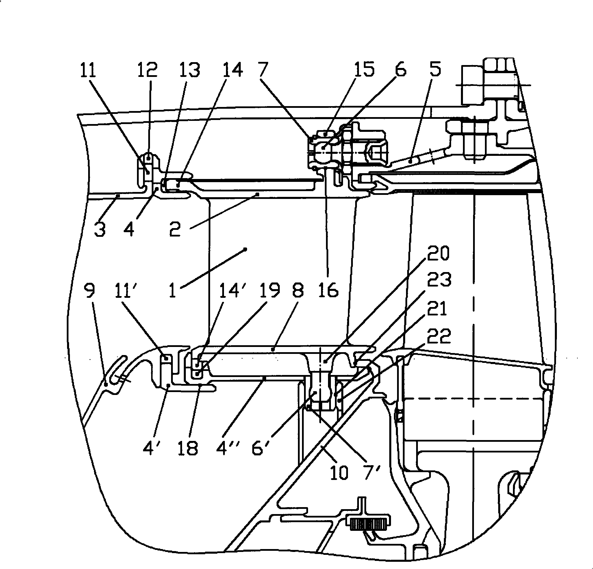
[0010] The gas turbine engine turbine guider connection structure of the present invention comprises the inner and outer edge plates 8, 2 of the connection guider 1, the combustion chamber and the outer case 9, 3, the mounting rings 4, 4`, 4``, the turbine inner , Outer casing 10,5, hinge 6,6 ' and sleeve pipe 7,7 '.

[0011] The radial groove 11 at the front part of the mounting ring 4 is connected with the flange 12 on the casing 3 outside the combustion chamber, and is constrained in the axial direction and free in the radial direction. The axial ring groove 13 at the rear part of the mounting ring 4 cooperates with the guide flange 14, free in the axial direction and constrained in the radial direction. In this way, the axial and radial directions between the guide 1 and the casing 3 outside the combustion chamber are free.

[0012] The axial positioning hole 16 on the lug 15 at the rear of the guider outer edge plate 2 is connected with the hinge 6 fixed on the outer cas...


PUM


Abstract

The present invention relates to a gas turbine engine turbine guide apparatus connecting structure which comprises a guide apparatus, an internal edge plate and an external edge plate of the guide apparatus, a combustion chamber casing, a turbine casing, a guide apparatus internal casing, an installing ring and a sleeve. In the key points of the gas turbine engine turbine guide apparatus connecting structure, an axial positioning hole of a lifting eye at the guide apparatus is connected with a gemel which is fixed at a turbine external casing by the sleeve; a radial slot at the front part of the installing ring is matched and connected with a flange at the combustion chamber casing; an axial ring slot at the back part of the installing ring is matched with the flanged lip of the guide apparatus; the gemel under a tubular shaft neck at the internal edge plate is arranged in a columnar slot by the sleeve. The axial and radial displacements of the guide apparatus of the present invention can be compensated, and the gas turbine engine turbine guide apparatus connecting structure can not produce overlarge heat stress, is compact for installing and matching, can realize gas closure well and reduces the leakage of high temperature gas.

Description

Technical field: [0001] The invention relates to a gas turbine engine, in particular to a connection structure of a turbine guider of the gas turbine engine. Background technique: [0002] The core components of a gas turbine engine include a compressor, a combustion chamber, and a turbine. The turbine is composed of a stator and a rotor. The rotor is a working wheel, and the stator includes a turbine guide. Although the turbine guide is a stationary part, it works in a high-temperature gas flow, and the working conditions are very harsh. Under high temperature, the mechanical properties of the material decline rapidly. In addition, due to the direct contact between the parts and the gas flow, the free oxygen in the gas has a strong oxidation and corrosion effect on the surface of the blade. Due to the inhomogeneity of the temperature field of the gas flow, the heating of the turbine guide and its adjacent parts is not uniform. In addition, the size and material of each par...

Claims


Application Information

Patent Timeline
Patent Type & Authority Applications(China)
IPC IPC(8): F01D9/04F01D25/24
Inventor 陈竞炜付晟李鑫
Owner CHINA AVIATION POWER MACHINE INST
Why Eureka
Try Eureka