Continuous heat supply phase-change energy storage defrosting system

A phase-change energy storage, non-interrupted technology, used in indirect heat exchangers, heat storage equipment, heat exchanger types, etc., can solve problems such as poor unit stability and reliability, slow defrosting speed, and affecting room comfort. , to achieve the effect of high energy utilization, improved comfort, and improved defrosting speed

Inactive Publication Date: 2009-01-07
HARBIN INST OF TECH
View PDF0 Cites 34 Cited by
  • Summary
  • Abstract
  • Description
  • Claims
  • Application Information

AI Technical Summary

Problems solved by technology

[0008] The purpose of the present invention is to solve the defrosting method of the existing air source heat pump, because the defrosting energy of the hot gas mainly comes from the compressor, the stability and reliability of the unit are poor, the

Method used


Image

  • Continuous heat supply phase-change energy storage defrosting system

Examples


specific Embodiment approach 1

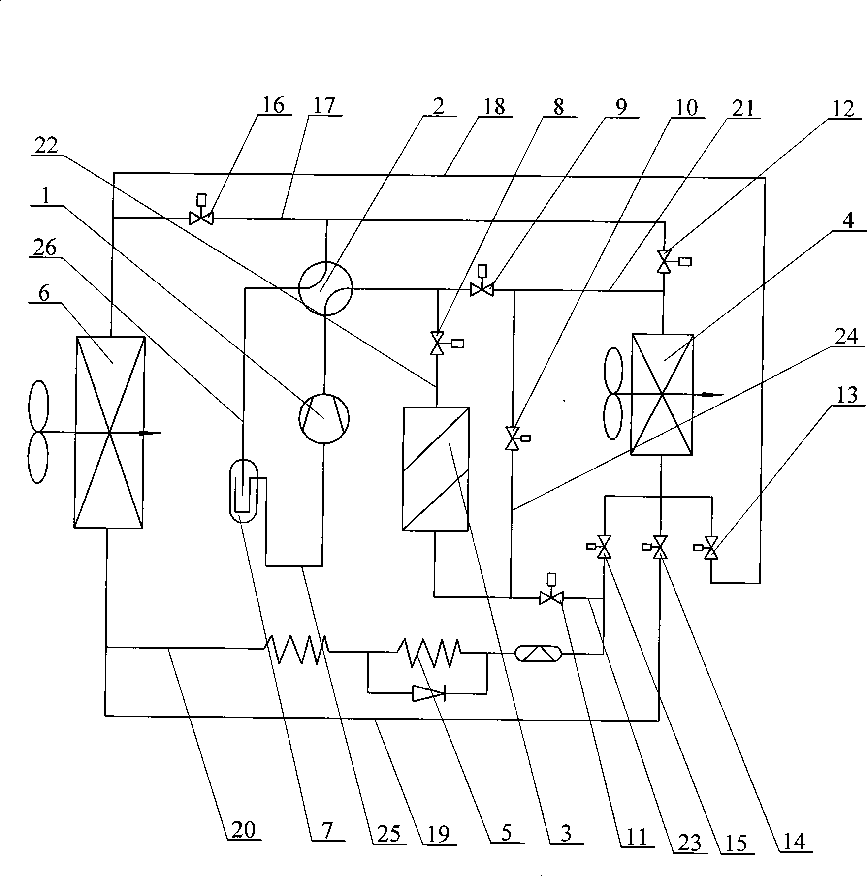
[0012] Specific implementation mode one: combine figure 1 Describe this embodiment, the energy storage defrosting system of this embodiment includes a compressor 1, a four-way reversing valve 2, an indoor unit 4, a capillary tube 5, an outdoor unit 6, a gas-liquid separator 7, a phase change heat accumulator 3, First valve 8, second valve 9, third valve 10, fourth valve 11, fifth valve 12, sixth valve 13, seventh valve 14, eighth valve 15, ninth valve 16, first pipeline 17 , the second pipeline 18, the third pipeline 19, the fourth pipeline 20, the fifth pipeline 21, the sixth pipeline 22, the seventh pipeline 23 and the eighth pipeline 24; the input of the compressor 1 The end is connected with the output end of the gas-liquid separator 7, the output end of the compressor 1 is connected with the first interface of the four-way reversing valve 2, and the second interface of the four-way reversing valve 2 is connected with the first pipeline 17. connection, the two ends of the...

specific Embodiment approach 2

[0013] Specific implementation mode two: combination figure 1 Describe this embodiment, the difference between this embodiment and specific embodiment 1 is: the energy storage defrosting system of this embodiment also includes a ninth pipeline 25; both ends of the ninth pipeline 25 are separated from the gas-liquid The output terminal of the device 7 is connected with the input terminal of the compressor 1 for convenient connection.

specific Embodiment approach 3

[0014] Specific implementation mode three: combination figure 1 Describe this embodiment, the difference between this embodiment and specific embodiment 1 is: the energy storage defrosting system of this embodiment also includes a tenth pipeline 26; the two ends of the tenth pipeline 26 are separated from the gas-liquid The input end of the device 7 is connected with the third interface of the four-way reversing valve 2, which is convenient for connection.

[0015] The invention is a new system that organically combines air source heat pump technology and phase change energy storage technology based on the idea of ​​energy time-space transfer. This system uses air source heat pump to extract heat from the air in winter and store it in the phase change heat accumulator. When defrosting is required, the stored heat is taken out for defrosting and heating for the room. The system operation mode can be divided into normal heating mode, heat storage mode and defrosting mode. Amon...


PUM


Abstract

The invention provides a non-intermittent phase-change heat storage defrosting system, which relates to an energy storage defrosting system. The defrosting system aims at solving the problems that an air source hot pump defrosting method has the poor stability and reliability of machine units and the rooms become less comfortable after heat supply is stopped. The defrosting system of the invention is characterized in that an indoor machine is connected with a first pipeline and a second pipeline; an outdoor machine is connected with a second pipeline and a third pipeline; the third pipeline is respectively connected with the indoor pipeline and the outdoor pipeline; a fourth pipeline and a fifth pipeline are respectively connected with the fist pipeline and the third pipeline; a compressor is connected with a gas-liquid separator; a four-way directional valve is respectively connected with the first and the fifth pipelines, the gas-liquid separator and the compressor; the phase-change heat storage device is connected with the fifth and the fourth pipelines through a sixth pipeline and a seventh pipeline; an eighth pipeline is respectively connected with the fifth and seventh pipelines; a first valve, a second valve, a third valve, a fourth valve, a fifth valve, a sixth valve, a seventh valve, an eighth valve and a ninth valve are respectively arranged on the fifth pipeline, the sixth pipeline, the seventh pipeline, the eighth pipeline, the first pipeline, the second pipeline, the third pipeline, the fourth pipeline and the first pipeline; a capillary pipe is arranged on the fourth pipeline. The defrosting system of the invention has good stability and reliability, high defrosting speed, and high comfort level of the room after the heat supply is stopped.

Description

technical field [0001] The invention relates to an energy storage defrosting system. Background technique [0002] The air source heat pump operates under the weather conditions of -5°C to 5°C, and the relative humidity (RH) is above 70%, and the surface of its outdoor heat exchanger is the most prone to frost. Frosting of the outdoor unit of the air source heat pump will lead to a decrease in evaporation temperature, a decrease in heating capacity, attenuation of fan performance, and increase in current, which will cause the air source heat pump unit to fail to work normally. Therefore, the periodic defrosting of the air source heat pump is a necessary link to ensure the normal operation of the unit. [0003] At present, air source heat pump defrosting methods include thermal defrosting and non-thermal defrosting. The shortcomings of each defrosting method are as follows: [0004] 1. Non-thermal defrosting is to suppress frosting through special treatment on the surface ...

Claims


Application Information

Patent Timeline
IPC IPC(8): F25B47/02F28D20/02
CPCY02E60/145Y02E60/14
Inventor 姜益强姚杨胡文举马最良
Owner HARBIN INST OF TECH
Why Eureka
Try Eureka