Interval adjusting construction of moving component

A technology of gap adjustment and moving parts, applied in the parts, instruments, casings and other directions of the instrument, it can solve the problems of not beautiful appearance, hard friction, uneven gap, etc., so as to reduce the possibility of hard friction and reduce the The effect of verticality and uniform gap

Active Publication Date: 2011-09-07
SHENZHEN MINDRAY BIO MEDICAL ELECTRONICS CO LTD
View PDF0 Cites 0 Cited by
  • Summary
  • Abstract
  • Description
  • Claims
  • Application Information

AI Technical Summary

Problems solved by technology

[0003] However, the existing height adjustment mechanism has the following disadvantages: 1) The gap C' between the appearance sleeve and the fixed host shell cannot be adjusted, so the appearance sleeve 6', support and lifting structure 5' require high verticality and processing Assembly requirements; 2) In order to reduce the verticality and assembly requirements of the support and lifting structure and to prevent interference between the two when the appearance sleeve moves up and down, it is necessary to leave a large gap between the appearance sleeve and the main engine shell, so that There will be eccentricity between the appearance sleeve and the host shell, that is, the so-called uneven gap problem, which may also cause interference and hard friction; 3) When the roundness of the appearance sleeve and the through hole of the host shell is not high, the gap is not Even, the appearance is not beautiful enough

Method used


Image

  • Interval adjusting construction of moving component
  • Interval adjusting construction of moving component
  • Interval adjusting construction of moving component

Examples


Embodiment Construction

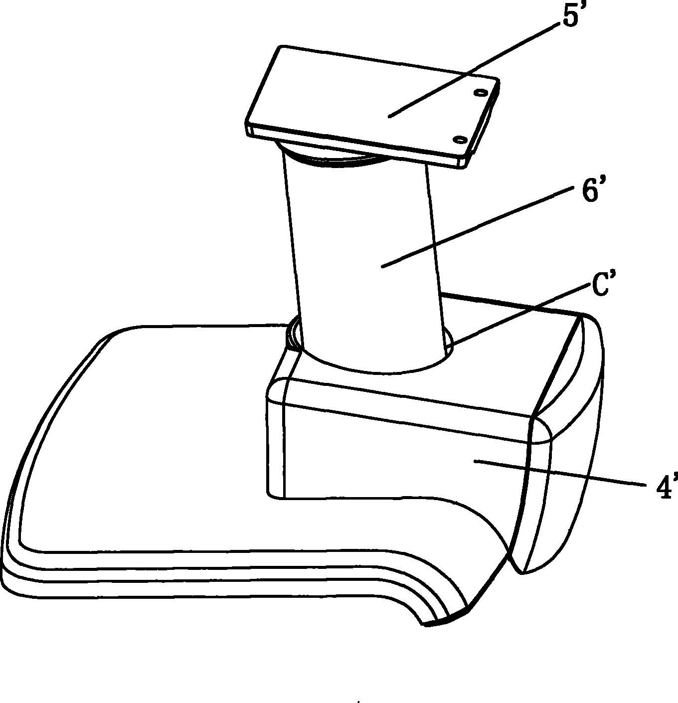
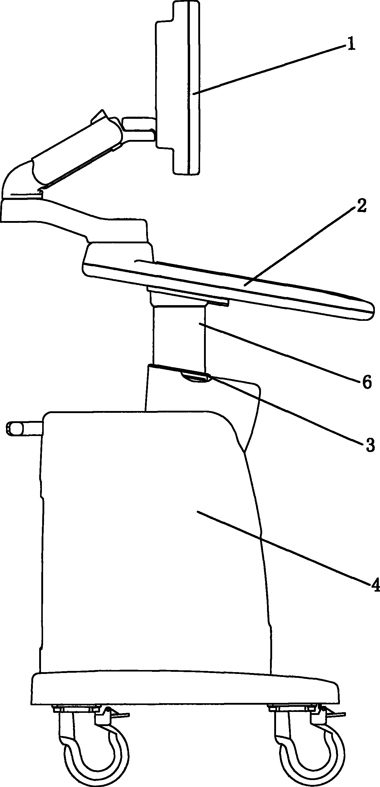
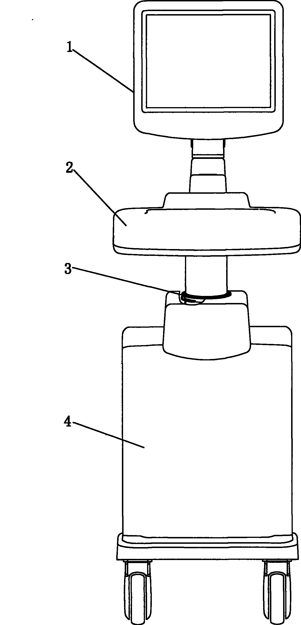
[0021] see Figure 2 to Figure 8 The gap adjustment structure of the moving parts in this embodiment includes a first part 4, a second part 6 and an adjustment ring 3. The first part has a mounting hole, and the adjustment ring is fitted into the mounting hole and covers the second part.

[0022] The first component 4 has a casing 41 , and the casing 41 has a first surface 411 , a second surface 412 and a mounting hole 413 passing through the first and second surfaces 411 , 412 . The second component 6 is a cylinder, which is inserted into the mounting hole 413 of the first component and can move axially relative to the first component 4 . The adjustment ring 3 is made of soft material, such as soft rubber, so that it can be deformed when extruded by external force. The section of the adjustment ring 3 is I-shaped, and the adjustment ring 3 has a body 31 , a first clamping edge 32 and a second clamping edge 33 . The main body 31 is cylindrical, with a through hole 311 axiall...


PUM


Abstract

The invention discloses a moving element clearance adjustment structure which comprises a first element, a second element and an adjusting ring which is provided with a radial through hole; the first element is provided with a housing which comprises a first surface, a second surface and a mounting hole which passes through the first surface and the second surface; the second element is inserted into the mounting hole and can axially move in relation to the first element; the adjusting ring is arranged in the mounting hole and positioned on a limit surface of the housing for avoiding the adjusting ring from axially falling off the mounting hole; the through hole of the adjusting ring is sheathed on the second element; the adjusting ring keeps radial clearances with the mounting hole, the through hole and the second element. When the roundness of the second element is not high, the second element generates slight friction with the adjusting ring to cause the adjusting ring to perform slight radial movement, which causes the clearance between the second element and the adjusting ring to become uniform and removes the friction, thus greatly reducing the verticality and roundness requirements of the second element and a support and lifting structure for driving the second element to axially go up and down and causing the assembly production to be easier and simpler.

Description

technical field [0001] The present invention relates to a kinematic structure. Background technique [0002] The keyboard of the vehicle-mounted ultrasound instrument needs to be adjusted in height in order to be suitable for operators of different heights or different operating postures (sitting or standing postures) of the operators. Height adjustment is usually achieved by lifting the keyboard, and the keyboard support structure (including the appearance sleeve) also moves up and down accordingly. Such as figure 1 As shown, the existing height adjustment mechanism includes an appearance sleeve 6', a host shell 4' and a support and lifting structure 5' that drives the appearance sleeve 6' to lift, and the appearance sleeve 6' directly passes through the main frame shell 4'. Through holes, in order to ensure that there is no hard friction between the appearance sleeve and the host shell and keep the appearance sleeve and the keyboard moving up and down smoothly, it is nec...

Claims


Application Information

Patent Timeline
Patent Type & Authority Patents(China)
IPC IPC(8): G12B5/00G12B9/08
Inventor 朱大惠陈志武肖训华
Owner SHENZHEN MINDRAY BIO MEDICAL ELECTRONICS CO LTD
Why Eureka
Try Eureka