Coiled tubing four-gate blowout preventer

A technology of blowout preventer and four rams, applied in wellbore/well components, earthwork drilling, sealing/isolation, etc., can solve problems such as poor sealing, failure of semi-sealing device, failure, etc., to avoid man-made damage , prolong the service life, reduce the effect of hard friction

Inactive Publication Date: 2020-12-04
曲睿婕
View PDF8 Cites 0 Cited by
  • Summary
  • Abstract
  • Description
  • Claims
  • Application Information

AI Technical Summary

Problems solved by technology

The existing problems are as follows: First, the coiled tubing will shrink in diameter during long-term back-and-forth use, that is, the diameter will shrink, and the diameter of the half-sealed ram will not change accordingly, which will cause poor sealing. Case
Second, during the construction process under pressure, the half-sealed ram will cause hard friction due to the up and down movement of the coiled tubing, causing it to fail quickly
Third, during the construction process, since the innermost side of the semi-sealed ram is provided with rubber, the rubber is used to contact the outer wall of the coiled tubing to achieve sealing, but due to human reasons during the operation, the semi-sealed ram will protrude accidentally The rubber is knocked off, causing the failure of the semi-sealed device

Method used


Image

  • Coiled tubing four-gate blowout preventer
  • Coiled tubing four-gate blowout preventer
  • Coiled tubing four-gate blowout preventer

Examples


Embodiment 2

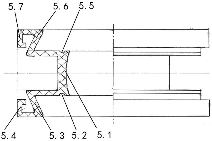
[0032] Embodiment 2, the difference from Embodiment 1 is: the section of the side of the setting expansion side (5.1) of the present invention in contact with the coiled tubing is an arc-shaped structure, and the section of the other side is a protrusion that is conducive to rebound Arc structure.

[0033] The method of use is the same as that of Example 1, the difference is: as the hydraulic pressure rises, the setting expansion side (5.1) expands in one direction under the action of pressure to form a cup seal structure, so that it is tight and continuous The outer wall of the tubing forms a seal; while the cross-section of the side in contact with the coiled tubing is an arc-shaped structure, the opposite direction forms a raised bowl-bottom shape.

Embodiment 3

[0034] Embodiment 3, the difference from Embodiments 1 and 2 is that the setting expansion side (5.1) of the present invention is a three-stage structure, and the section of the side in contact with the coiled tubing is an arc structure, a planar structure and an arc shape The structure consists of three sections, and the middle section is a planar structure.

[0035] In this way, the plane structure in the middle is better combined with the outer wall of the coiled tubing, forming a larger sealing surface and a longer-lasting sealing effect.


PUM


Abstract

The invention relates to a coiled tubing four-gate blowout preventer. According to the technical scheme, an expandable semi-sealed rubber cylinder is installed in the center of a blowout preventer body; the self-locking end of the tail is fixed to the blowout preventer body through a rubber opening pressing ring to form an annular cavity; a semi-sealed expansion control block is fixed to the outerside of the blowout preventer body; an oil inlet buffer groove and an oil outlet buffer groove are formed in the inner side of the blowout preventer body; and the oil inlet buffer groove correspondsto the expandable semi-sealed rubber cylinder of the blowout preventer body. The coiled tubing four-gate blowout preventer has the advantages that the expandable semi-sealed rubber cylinder is of an integral structure and is fixed into the special-shaped cavity of the blowout preventer body through the rubber opening pressing ring, in the using process, the expandable semi-sealed rubber cylinder can be self-locked to the blowout preventer body through pressing, the other side of the expandable semi-sealed rubber cylinder expands to make contact with the outer wall of a coiled tubing for sealing, the pressure of gas or liquid inside and outside the expandable semi-sealed rubber cylinder is balanced, leakage is not likely to happen, use is more reliable, and the service life of the expandable semi-sealed rubber cylinder is prolonged.

Description

technical field [0001] The invention relates to a coiled tubing four-ram blowout preventer. Background technique [0002] In the construction process of coiled tubing, the 4FZ blowout preventer, that is, the four-ram blowout preventer, is a safety protection device that must be installed. In this device, the half seal is the most important safety protection in the construction process. Device, the existing semi-sealed device, with reference to the Chinese patent document publication number 201915889U, the patent name is the semi-sealed device mentioned in "Hydraulic Control Four Ram BOP": a pair of semi-sealed rams are symmetrically connected by two piston rods It is fixed on the front ends of the two semi-sealed pistons, and the two semi-sealed pistons are respectively located in the two semi-sealed liquid cylinders, and the two semi-sealed liquid cylinders are symmetrically fixed at the lower end of the housing and located below the two suspension liquid cylinders. When i...

Claims


Application Information

Patent Timeline
Patent Type & Authority Applications(China)
IPC IPC(8): E21B33/06
CPCE21B33/061
Inventor 不公告发明人
Owner 曲睿婕
Why Eureka
Try Eureka