A clutch wear indicator plate structure

An indicator plate and clutch technology, applied in the field of clutch wear indicator plate structure, can solve the problems of easy fatigue failure, easy corrosion, and vehicle vibration.

Active Publication Date: 2017-09-26
SINO TRUK JINAN POWER
View PDF5 Cites 0 Cited by
  • Summary
  • Abstract
  • Description
  • Claims
  • Application Information

AI Technical Summary

Problems solved by technology

[0002] At present, the indicator plate in the clutch wear indicator device can only move in one direction, but the clutch is a vulnerable part and needs to be replaced frequently. The installation tolerance of the clutch is relatively large, so that the indicator plate must move in both directions if the replacement is to be initialized accurately; in addition, the indicator The chip is used in harsh working conditions, prone to rust, long-term vibration with the vehicle, easy to loose due to fatigue failure, and poor reliability

Method used


Image

  • A clutch wear indicator plate structure

Examples


Embodiment Construction

[0016] In order to clearly illustrate the technical features of the solution, the solution will be described below through specific implementation modes.

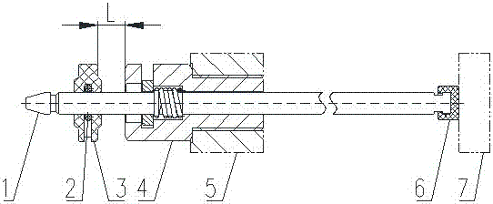
[0017] Such as figure 1 As shown, the present invention is a clutch wear indicator plate structure, including a straight rod 1, the straight rod 1 is made of stainless steel, the axis of the straight rod 1 is in the same direction as the axis of the clutch booster cylinder, and the two ends of the straight rod 1 are respectively located in the cavity of the booster cylinder Inside and outside, the end of the straight rod 1 located inside the cavity of the booster cylinder is located at the limit point of the movement position of the booster cylinder piston 7 under the touch of the booster cylinder piston 7 .

[0018] The end of the straight rod 1 located outside the booster cylinder cavity is provided with an indicator sheet 3, specifically, the end of the straight rod 1 located outside the booster cylinder cavity is provid...


PUM


Abstract

The invention discloses a clutch wear indicator plate structure, which comprises a straight rod made of stainless steel, the axis of the straight rod is in the same direction as the axis of the clutch booster cylinder, and the two ends of the straight rod are respectively located inside and outside the cavity of the booster cylinder; There is an indicator piece located at one end outside the cavity of the booster cylinder. The indicator piece is a disc-shaped plastic part. A through hole is provided in the middle of the indicator plate surface for socketing on the straight rod; the indicator piece is provided with an inner groove from the side to the center. A steel wire circlip is provided, and the steel wire circlip is sleeved on the straight rod and has an interference fit with the straight rod; the cylinder body of the booster cylinder is provided with a fixing seat, and the straight rod passes through the fixing seat; both the indicator plate and the fixing seat are provided with The measuring surface perpendicular to the axis is used to measure the distance between the indicator plate and the fixing seat. The beneficial effects of this scheme can be known from the description of the above scheme. The structure is simple, reliable in use, can move in two directions, has no rust under harsh working conditions, and has no looseness due to long-term vibration.

Description

technical field [0001] The invention relates to a clutch control device, in particular to a clutch wear indicator plate structure. Background technique [0002] At present, the indicator plate in the clutch wear indicator device can only move in one direction, but the clutch is a vulnerable part and needs to be replaced frequently. The installation tolerance of the clutch is relatively large, so that the indicator plate must move in both directions if the replacement is to be initialized accurately; in addition, the indicator The chip is used in harsh working conditions, prone to rust, long-term vibration with the vehicle, easy to loose due to fatigue failure, and poor reliability. Contents of the invention [0003] The present invention aims at the deficiencies of the prior art, and provides a clutch wear indicator plate structure with simple structure, reliable use, bidirectional movement, no rust under harsh working conditions, and no looseness due to long-term vibratio...

Claims


Application Information

Patent Timeline
Patent Type & Authority Patents(China)
IPC IPC(8): F16D13/58
Inventor 范彩红许佳成张子强崔慧萍李文君薛秋生杨国玉
Owner SINO TRUK JINAN POWER
Why Eureka
Try Eureka