
Electric appliance dynamic test apparatus adopting high-speed camera

A high-speed camera, dynamic testing technology, applied in the direction of using optical devices, machine/structural components testing, measuring devices, etc., can solve problems such as difficulty in testing electrical dynamic process, and achieve the effect of improving dynamic indicators

Inactive Publication Date: 2010-07-21
FUZHOU UNIV
View PDF0 Cites 0 Cited by
  • Summary
  • Abstract
  • Description
  • Claims
  • Application Information

AI Technical Summary

Problems solved by technology

[0005] The invention solves the problem of difficulty in testing the dynamic process of electrical appliances, improves the dynamic indicators of electrical appliances and their products, and can be applied not only to product detection, but also to new product development and research on dynamic characteristics of electrical appliances

Method used


Image

  • Electric appliance dynamic test apparatus adopting high-speed camera
  • Electric appliance dynamic test apparatus adopting high-speed camera
  • Electric appliance dynamic test apparatus adopting high-speed camera

Examples


Embodiment Construction

[0010] The present invention will be further described below in conjunction with the accompanying drawings and embodiments.

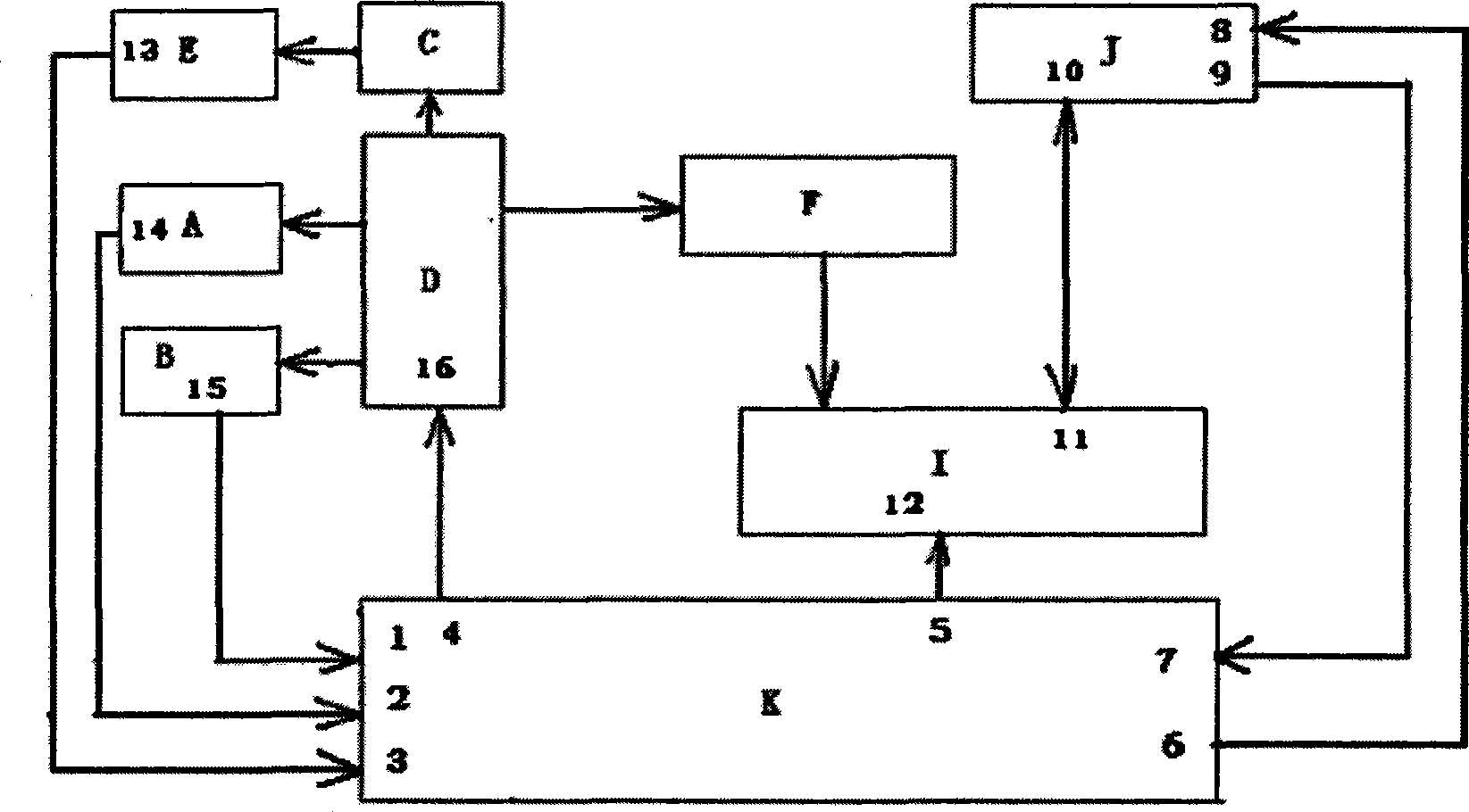
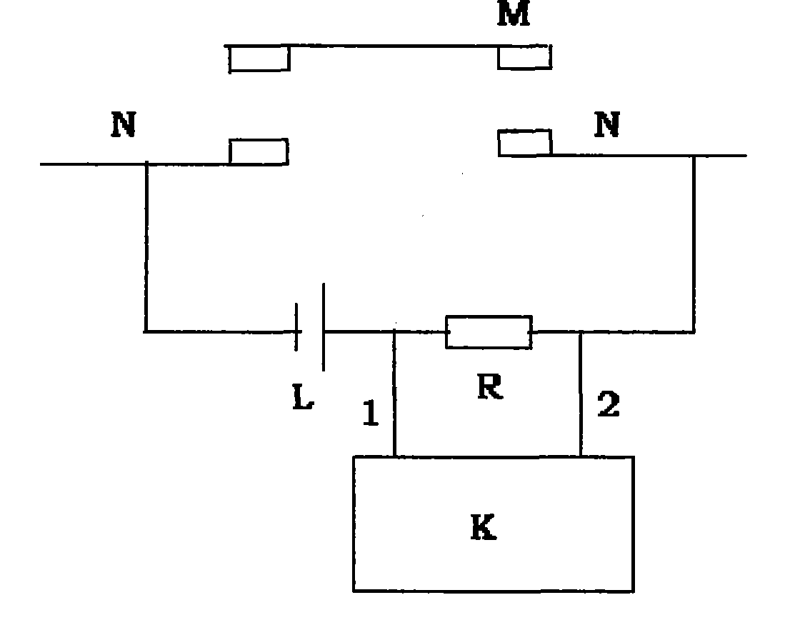
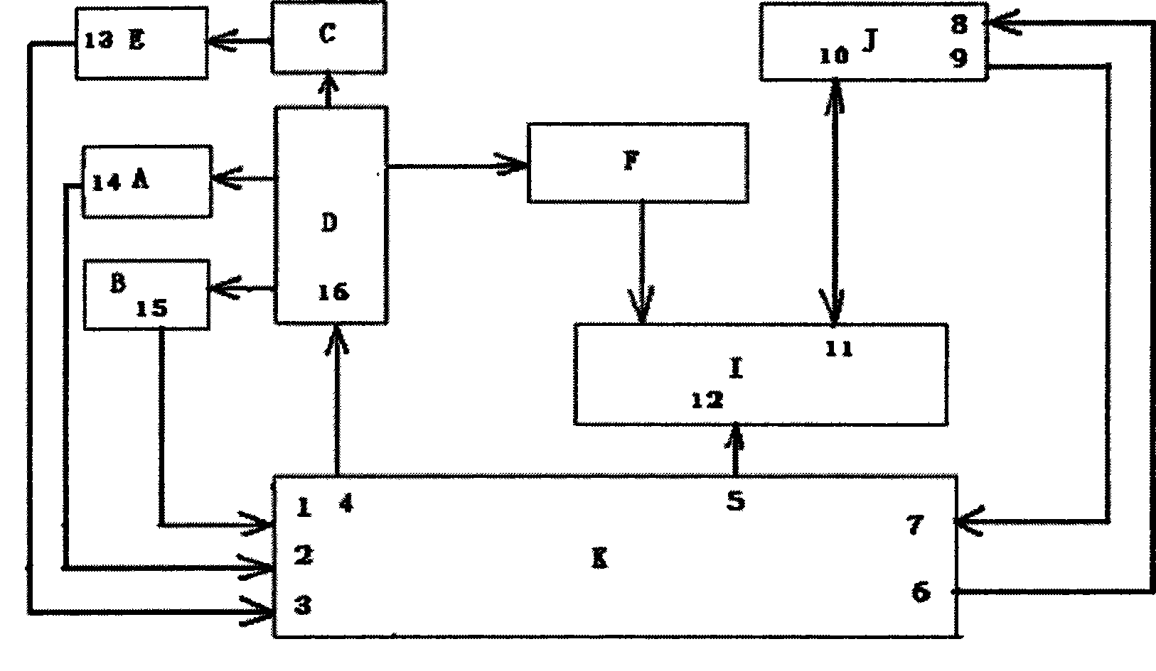
[0011] from figure 1 As can be seen, the electric appliance dynamic testing device that adopts high-speed camera of the embodiment of the present invention, it comprises high-speed camera CCD camera head [F], high-speed camera main frame [I], signal acquisition and control circuit [K], computer [J], voltage sensor [ A], the current sensor [B], the action mechanism of the electrical appliance under test [D], the contact system of the electrical appliance under test [C], the contact action signal circuit [E]; it is characterized in that: the output terminal of the voltage sensor [A] [ 14], the output terminal [15] of the current sensor [B] and the output terminal [13] of the contact action signal circuit [E] are respectively connected to the voltage signal input terminal [2] of the signal acquisition and control circuit [K], the current The signal input ...


PUM


Abstract

An electric apparatus dynamic testing device which adopts a high-speed camera and comprises a CCD camera head (F) of the high-speed camera, a host (I) of the high-speed camera, a signal acquisition and control circuit (K), a computer (J), a voltage sensor (A), a current sensor (B), an action mechanism (D) of an electric apparatus to be measured, a contact system (C) of the electric apparatus to be measured and a contact action signal circuit (E); the electric apparatus dynamic testing device realizes the test of the dynamic process and the characteristics of the electric apparatus by shootingand processing motion displacement images of the action mechanism of the electric apparatus.

Description

technical field [0001] The invention relates to a dynamic testing device for electrical appliances using a high-speed camera, which belongs to the technical field of testing high-voltage and low-voltage switching electrical appliances. Background technique [0002] Miao Xiren, Zhang Peiming, etc. published the article "Development of Dynamic Test Device for Optical Electromechanical Electromagnetic Appliances" in the fourth issue of "New Technology of Electrical Engineering and Electric Energy" in 2001. It is introduced that thin slices are embedded on the skeleton of the movable parts of the electromagnetic system, and the laser parallel light source is used. The movement of the movable part is converted into a beam of moving parallel light, and a high-speed linear array CCD is used to convert the moving beam into light-receiving pixels that move rapidly along the line array, and the CCD will output video signals that change with the movement of the movable part for electrom...

Claims


Application Information

Patent Timeline
Patent Type & Authority Patents(China)
IPC IPC(8): G01B11/02G01R31/00G01M19/00G01M99/00
Inventor 张培铭陈德为鲍光海江和吴功祥
Owner FUZHOU UNIV
Learn More