Automatic winding device of mechanical clock

A technology for automatic winding and clocks, which is applied in the field of clocks and watches, and can solve problems such as inapplicability

Inactive Publication Date: 2009-01-14
牟昌山
View PDF0 Cites 5 Cited by
  • Summary
  • Abstract
  • Description
  • Claims
  • Application Information

AI Technical Summary

Problems solved by technology

The mechanical automatic winding system uses a metal oscillating weight inside the watch. Its operating principle is to use the movement of the wearer's arm to make the metal oscillating weight in the automatic system sw

Method used


Image

  • Automatic winding device of mechanical clock
  • Automatic winding device of mechanical clock

Examples


Embodiment Construction

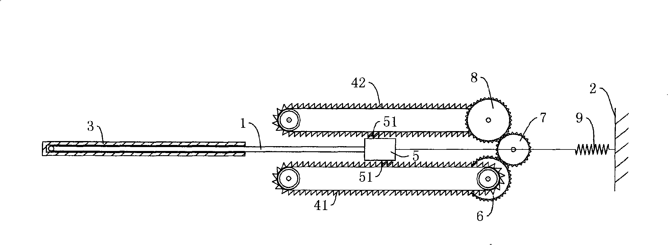
[0013] like figure 1 As shown, the automatic winding device for mechanical clocks and watches includes a watch body 2, in which a clockwork shaft gear 7 for winding is provided, and in the watch body 2 is provided a temperature-sensitive memory that can sense temperature changes and produce stretching Metal strip 1, a unidirectional push device for making the spring shaft gear 7 rotate in one direction is provided between the temperature-sensitive memory metal strip 1 and the clockwork shaft gear 7, and the temperature-sensitive memory metal strip 1 can be made of a conventional memory alloy The temperature-sensitive memory metal strip 1 senses temperature changes and expands and contracts to push the one-way push device, so that the mainspring shaft gear 7 rotates in one direction to realize automatic winding. With this structure, no matter whether the mechanical clock is in motion or static, as long as There are differences and changes in the external temperature, and the au...


PUM


Abstract

The invention discloses an automatic mechanical clock winding device, which comprises a mainspring shaft gear arranged in a clock body, a temperature-sensitive memory metal bar which can sense temperature changes and stretch or reduce in accordance and is arranged in the clock body, and a unidirectional pushing device which forces the mainspring shaft gear to rotate in one direction and is arranged between the temperature-sensitive memory metal bar and the mainspring shaft gear. The device of the invention can not only be applicable to automatic winding of mechanical clocks in working state but also be applicable to automatic winding of mechanical clocks in idle state.

Description

technical field [0001] The invention relates to the technical field of clocks and watches, in particular to an automatic winding device for mechanical clocks used for winding the mainspring of the mechanical clocks. Background technique [0002] At present, most of the ordinary mechanical clocks and watches used by people's doors must be wound manually at regular intervals to maintain their normal operation. The mechanical automatic winding system uses a metal oscillating weight inside the clock. Its operating principle is to use the movement of the wearer's arm to make the metal oscillating weight in the automatic system swing due to the gravity of the earth, and the metal oscillating weight does not rotate at all. Thereby pushing the levers and gears in the system to wind up the mainspring, so it can be seen that this automatic winding system is only suitable for watches. inapplicable. Contents of the invention [0003] The technical problem to be solved by the present...

Claims


Application Information

Patent Timeline
IPC IPC(8): G04B5/22
Inventor 牟昌山
Owner 牟昌山
Why Eureka
Try Eureka