

Radio-controlled timepiece and control method for a radio-controlled timepiece
A technology of radio waves and clocks, applied in clocks, radio-controlled timers, electromechanical clocks, etc., can solve the problems of deterioration of the receiving environment, inability to obtain time information, and increased power consumption, and achieve the effect of optimizing the binarization conditions.
- Summary
- Abstract
- Description
- Claims
- Application Information
AI Technical Summary
Problems solved by technology
Method used
Image

Examples
no. 1 Embodiment approach
[0075] Next, a radio-controlled timepiece 1 according to a first embodiment of the present invention will be described with reference to the drawings.
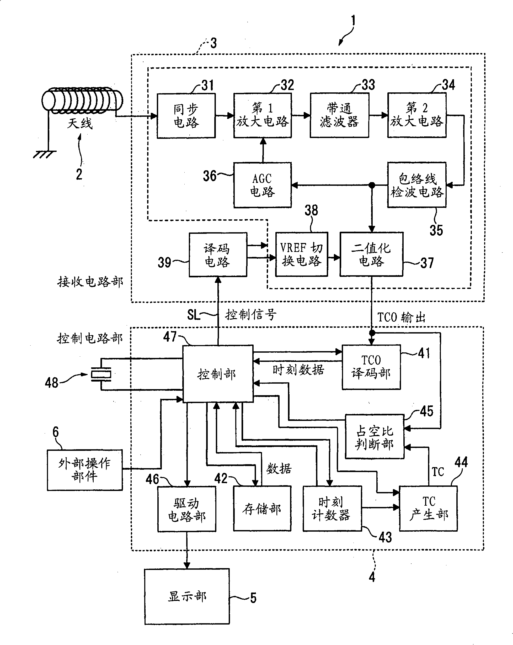
[0076] figure 1 It is a block diagram showing the configuration of the radio-controlled timepiece of the first embodiment.
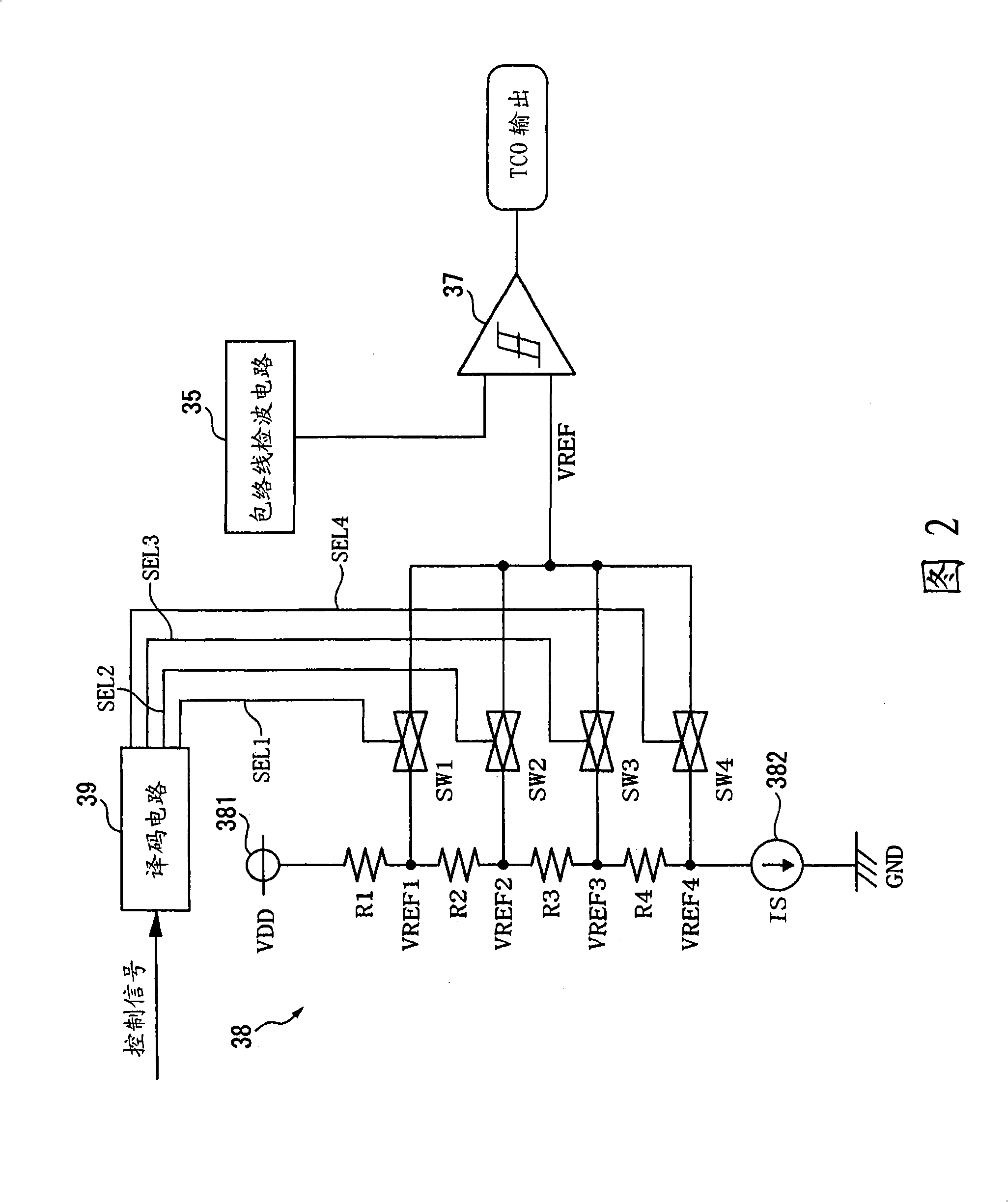
[0077] FIG. 2 is a circuit diagram showing configurations of a binarization circuit and a VREF switching circuit.
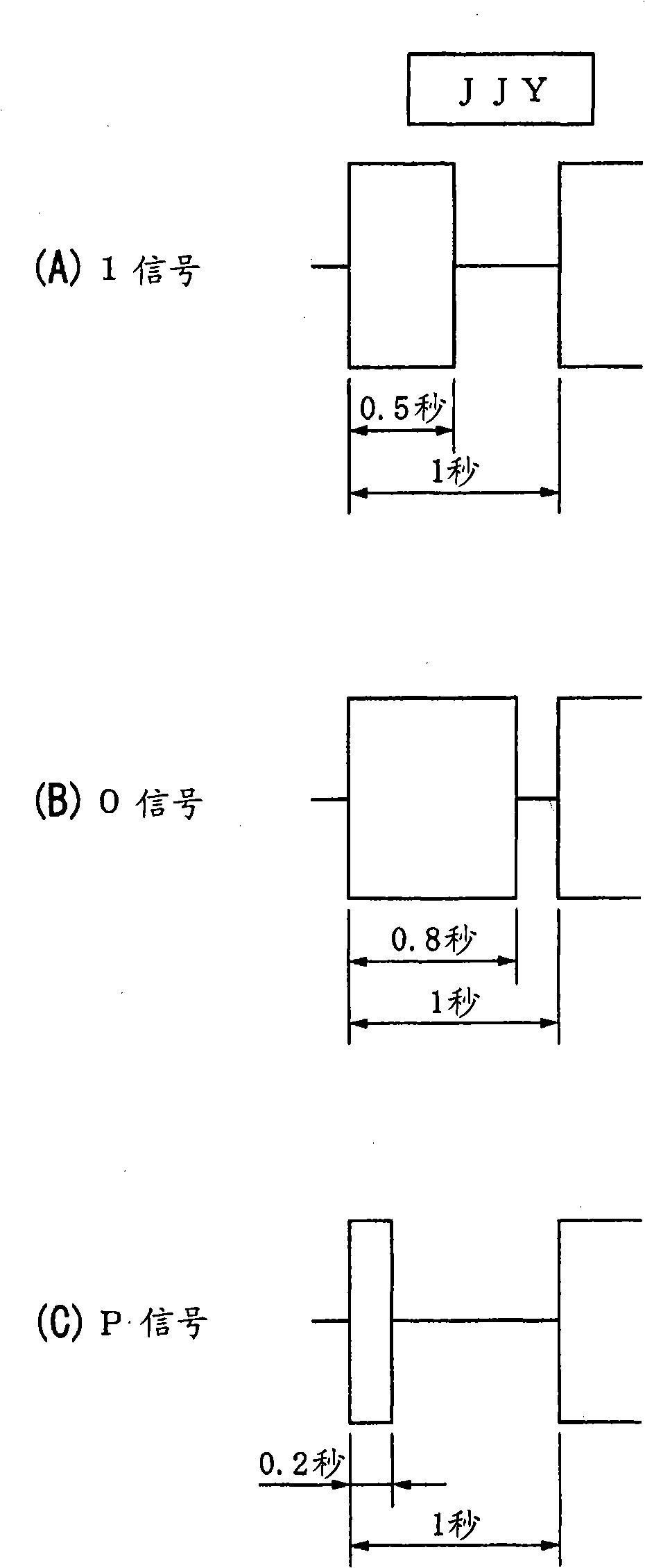
[0078] image 3 It is a graph showing the reception pulse duty ratio and amplitude change of each signal with respect to the Japanese standard radio wave "JJY".
[0079] Figure 4 It is a graph showing the reception pulse duty ratio and amplitude change of each signal with respect to the standard radio wave "WWVB" in the United States.
[0080] Figure 5 It is a graph showing the reception pulse duty ratio and amplitude change of each signal with respect to the German standard radio wave "DCF77".
[0081] Image 6 It is a graph showing the reception pulse duty ratio and amplitude cha...
no. 2 Embodiment approach
[0184] Next, a radio-controlled timepiece 1A according to a second embodiment of the present invention will be described with reference to the drawings.
[0185] Figure 13 It is a block diagram showing the structure of the radio-controlled timepiece of the second embodiment.
[0186] FIG. 14 is a graph showing the relationship between the AGC voltage and the gain in the first amplifier circuit.
[0187] 15 is a graph showing the relationship of the AGC voltage with respect to the input level of the received signal in each AGC characteristic switched by the AGC circuit.
[0188] In addition, when describing the radio-controlled timepiece 1A of the second embodiment, the same structures as those of the radio-controlled timepiece 1 of the above-mentioned first embodiment are assigned the same reference numerals, and their descriptions are simplified or omitted.
[0189] (1) Structure of radio-controlled timepiece 1A
[0190] exist Figure 13 Among them, the radio-controlled ...
no. 3 Embodiment approach
[0227] Next, a radio-controlled timepiece 1B according to a third embodiment of the present invention will be described with reference to the drawings.
[0228] Figure 18 It is a block diagram showing the structure of the radio-controlled timepiece 1B of the third embodiment. In the description of the radio-controlled timepiece 1B of the third embodiment, the same reference numerals are assigned to the same configurations as those of the radio-controlled timepieces 1 and 1A of the first and second embodiments described above, and their descriptions are simplified or omitted.
[0229] (1) Configuration of the radio-controlled timepiece 1B of the third embodiment
[0230] The radio-controlled timepiece 1B of the third embodiment is a timepiece in which the TC generator 44 of the radio-controlled timepiece 1 of the first embodiment is modified.
[0231] That is, the TC generating unit 44A in the radio-controlled timepiece 1B functions as the internal time reliability judging m...
PUM
 Abstract
Description
Claims
Application Information