Inductor-adjustable apparatus

A technology of inductance and electrical connection, applied in the field of inductance, can solve the problems of lower production efficiency, more production man-hours, and higher cost of positive electrodes, and achieve the effect of not affecting production efficiency, cheap inductance and wires, and increasing manufacturing costs

Inactive Publication Date: 2009-01-14
SHENZHEN SKYWORTH RGB ELECTRONICS CO LTD
View PDF0 Cites 1 Cited by
  • Summary
  • Abstract
  • Description
  • Claims
  • Application Information

AI Technical Summary

Problems solved by technology

However, this will consume more production man-hours, reduce production efficiency, and be detrimental to the pass-through rate of mass production; in this way, it is necessary to prepare a variety of inductance linear inductors for backup; at the same time, each TV may use different inductances. Different row linear inductance will cause inconvenience to the follow-up process and after-sales service
[0004] Using the above method 2, it is convenient to adjust the inductance online for nonlinear correction, but the price of the threaded adjustable inductance is twice the price of the replaced ordinary linear inductance, which will increase the cost of the positive electrode
[0005] In other applications other than CRT TVs, the above two methods are usually used when the inductance of the inductor needs to be changed, and there are also unfavorable factors that affect production efficiency and manufacturing costs.

Method used


Image

  • Inductor-adjustable apparatus
  • Inductor-adjustable apparatus
  • Inductor-adjustable apparatus

Examples


specific Embodiment approach 1

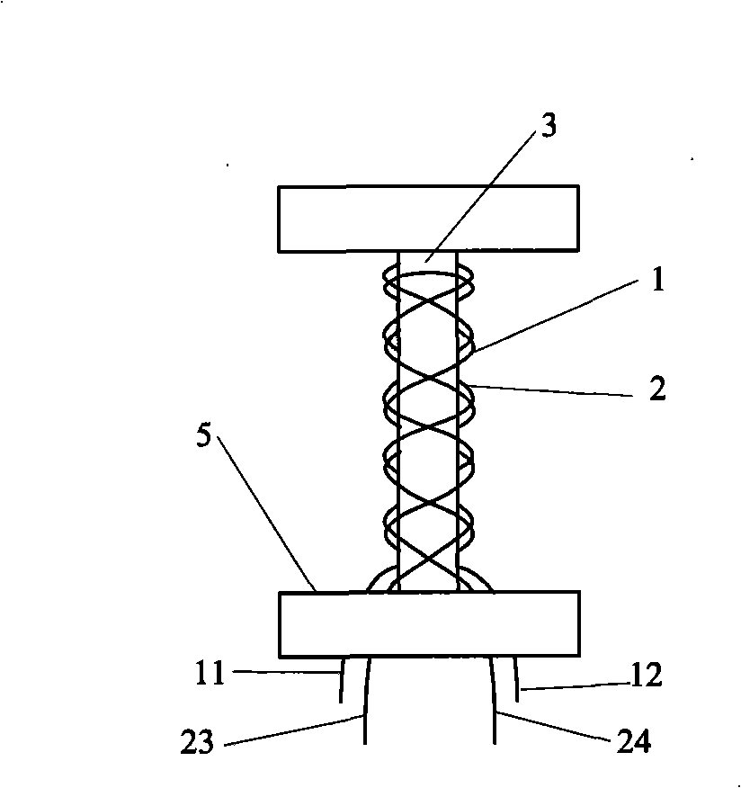
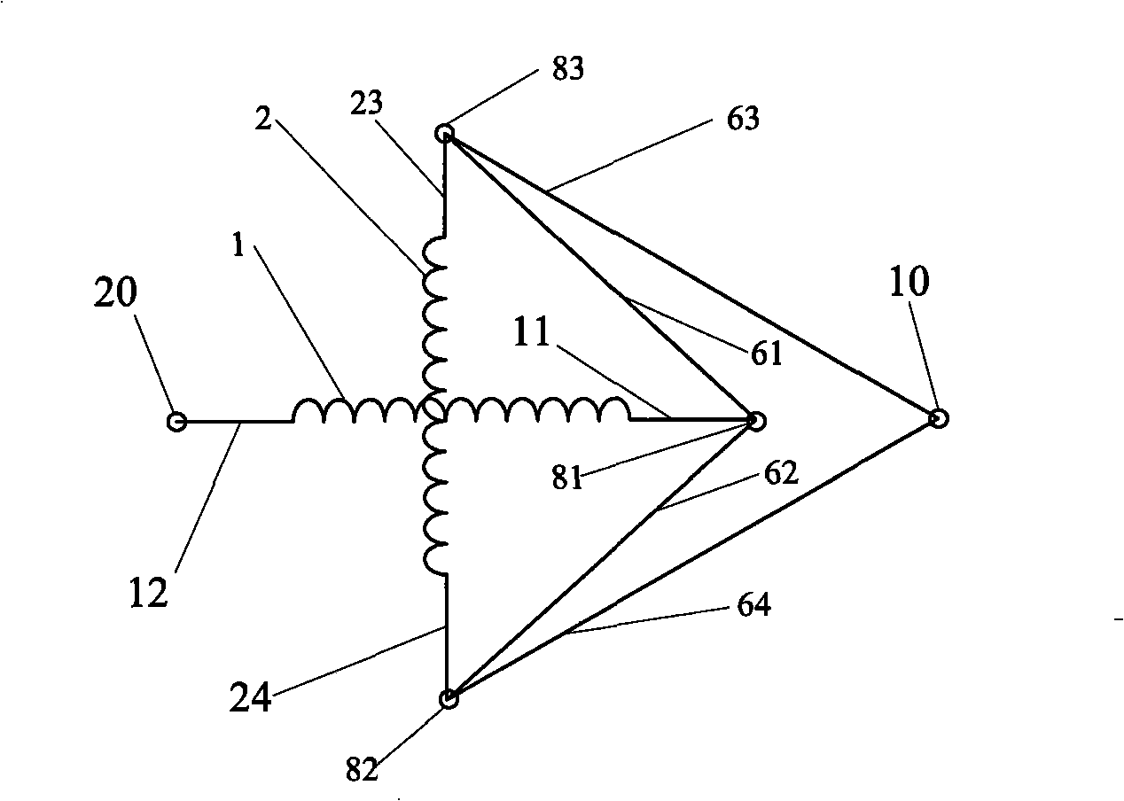
[0023] figure 1 , figure 2 , image 3 , Figure 4 and Figure 5 An embodiment of the adjustable inductance device of the present invention is shown. In order to clearly illustrate the connection relationship between the first inductor 1 and the second inductor 2, image 3 Will figure 1 The first inductance 1 and the second inductance 2 are deformed and expanded.

[0024] to combine figure 1 and image 3 , the adjustable inductance device includes a first inductor 1 , a second inductor 2 , a magnetic core 3 , an insulating base 5 , a first terminal 10 and a second terminal 20 . In order to clearly illustrate the positional relationship between the first inductor 1 and the second inductor 2, figure 1 The first terminal 10 and the second terminal (20) of the adjustable inductance device are not shown in the figure. The first inductance 1 and the second inductance 2 of the inductance adjustable device are concentrically wound on the magnetic core 3, the first pin 11 of ...

specific Embodiment approach 2

[0031] The inductance adjustable device of the specific embodiment can be obtained by removing the wires 61, 62, 63, 64 of the specific embodiment 1 inductance adjustable device.

[0032] refer to image 3 , when in use, establish the corresponding necessary connection between the third pin 23 and the fourth pin 24 of the second inductance 2, the first terminal 10, and the first pin 11 of the first inductance 1 as required. Can.

[0033] When different inductances are selected for the first inductance 1 and the second inductance 2, this adjustable inductance device can adjust and select 5 inductance values: refer to image 3 , 1. Connect the first terminal 10 and the first contact 81, at this moment, the inductance L=L of the adjustable inductance device 1 2. Connect the first terminal 10 and the second contact 82, the second terminal 20 and the third contact 83, or connect the first terminal 10 and the third contact 83, the second terminal 20 and the second contact 82, At ...

specific Embodiment approach 3

[0034] The equivalent circuit structure of the adjustable inductance device is as follows Figure 6 shown. Compared image 3 and Figure 6 , replace the wires 61, 62, 63, 64 of the inductance adjustable device in the first embodiment with switches K 1 、K 2 、K 3 、K 4 That is, the adjustable inductance device of this specific embodiment is obtained. When using, make the switch K as needed 1 、K 2 、K 3 、K 4 Just keep the corresponding open / closed state. The method of adjusting the inductance of the adjustable inductance device is the same as that in the second embodiment.


PUM


Abstract

The invention provides an inductance adjustable device, comprising a first inductance and a second inductance which can generate mutual inductance effect; the first pin of the first inductance can be electrically connected with the third pin or the fourth pin of the second inductance; the first terminal of the inductance adjustable device can be electrically connected with the third pin or the fourth pin of the second inductance; the second terminal of the inductance adjustable device is electrically connected with the second pin of the first inductance; the inductance adjustable device can simply change the connection relationship between the first inductance and the second inductance according to the requirement, realizes the adjustment of inductance quantity, has simple structure, hardly increases manufacture cost, has convenient usage, and does not affect production efficiency.

Description

technical field [0001] The invention relates to inductance, in particular to an adjustable inductance device. Background technique [0002] Inductor is a very commonly used electronic component. Usually the inductance of the inductor is constant. In some applications, it is necessary to change the inductance of the inductor. A typical example is the use of inductors in cathode ray tube (CRT) televisions. In an ultra-thin picture tube TV, the thickness of the picture tube is very thin, and accordingly, the deflection angle of the electron beam increases when the picture tube is working, for example, it may be increased from the original 90° to 120°, plus the sensitivity of the deflection coil increases, The initial inductance of the line high-voltage package and the discreteness of the errors of other components in the line will lead to the deterioration of the accuracy and consistency of the electron bombardment of the phosphor, and finally in a non-linear form, that is, ...

Claims


Application Information

Patent Timeline
Patent Type & Authority Applications(China)
IPC IPC(8): H01F21/12H01F29/02
Inventor 杨军治吴沛
Owner SHENZHEN SKYWORTH RGB ELECTRONICS CO LTD
Why Eureka
Try Eureka