Wireless power supply

A technology of wireless power supply and electronic devices, applied in the direction of circuit devices, electrical components, electromagnetic wave systems, etc., can solve the problem of low conversion efficiency of non-contact power supply, and achieve the effect of improving energy conversion efficiency

Inactive Publication Date: 2009-01-14
LITE ON ELECTRONICS (GUANGZHOU) LTD +1
View PDF0 Cites 25 Cited by
  • Summary
  • Abstract
  • Description
  • Claims
  • Application Information

AI Technical Summary

Problems solved by technology

[0004] In order to solve the problem of low conversion efficiency of the non-contact power supply used today, the present invention provides a wireless power supply device to improve the power conversion rate

Method used


Image

  • Wireless power supply
  • Wireless power supply
  • Wireless power supply

Examples


Embodiment Construction

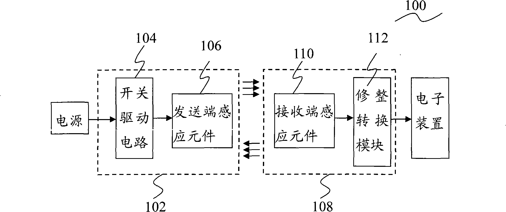
[0013] See figure 1 , figure 1 It is a block diagram of a wireless power supply device. The wireless power supply device 100 includes an energy transmitting unit 102 and an energy receiving unit 108. The energy transmitting unit 102 includes a switch driving circuit 104 and a transmitting end sensing element 106. The energy receiving unit 108 includes a receiving end sensing element 110 and a trimming conversion module 112. The energy transmitting unit 102 and the energy receiving unit 108 are respectively enclosed by a first housing and a second housing (not shown in the figure). In this embodiment, the transmitting-end inductive element 106 is a transmitting-end transformer, and the receiving-end inductive element 110 is a receiving-end transformer.

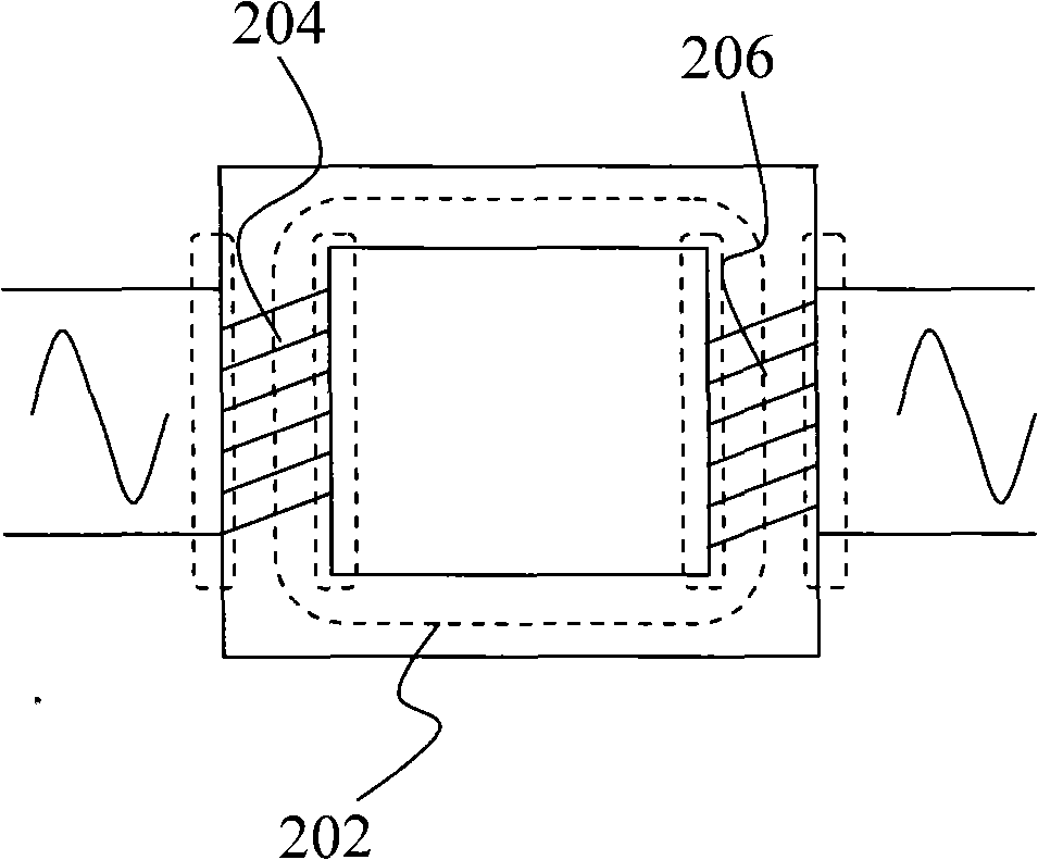
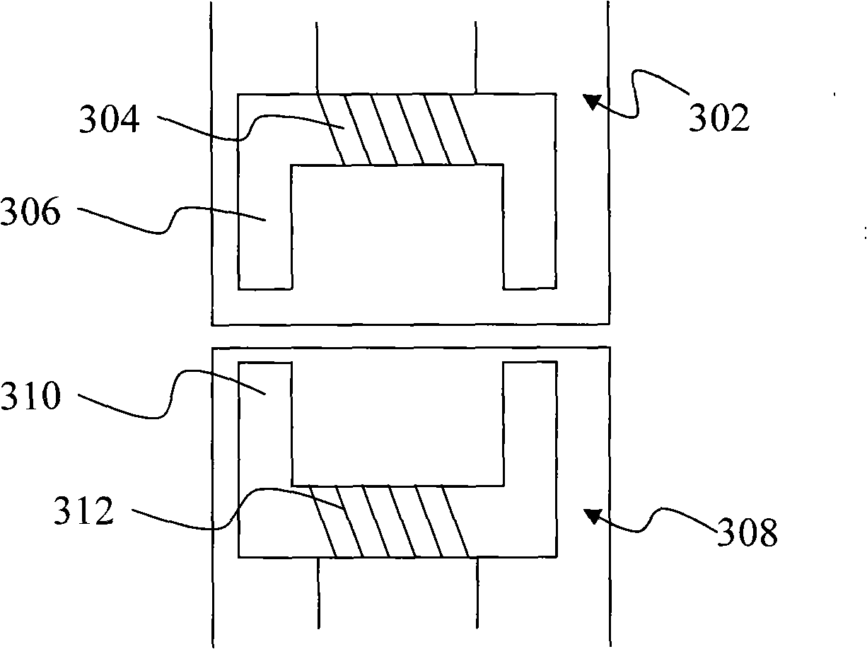
[0014] In the wireless power supply device of the present invention, a transformer generates high-frequency electromagnetic waves to realize energy transmission. Please refer to the principle Figure 2 to Figure 3 . Such as figure...


PUM


Abstract

The invention provides a wireless power supply device comprising an energy sending unit including a switch drive circuit and a sending end sensing element for converting the power into an electromagnetic wave and sending the electromagnetic wave out; an energy receiving unit including a receiving end sensing unit and a dressing conversion module for receiving the electromagnetic wave and converting into the alternating voltage current wave, again converting into the voltage source with correct voltage value by the dressing conversion module. The sending unit of the wireless power supply device provided by the invention can convert the power into the electromagnetic wave, the energy receiving unit receives the electromagnetic wave and converts the electromagnetic wave into the voltage source with correct voltage value, the energy sending unit connects with the energy receiving unit in wireless mode. The wireless device sends energy in form of electromagnetic wave, which greatly improves the energy conversion efficiency of the contactless power supply.

Description

Technical field [0001] The invention relates to a power supply device, in particular to a wireless power supply device. Background technique [0002] Generally, electronic devices obtain electrical energy from a power source, and they all need to obtain electrical energy through direct contact between conductors. The existing power sources mainly include AC power output through a power transformer and DC power output through a battery or accumulator, while electronic devices need to use When using AC power, a power cord needs to be connected to the power transformer. Due to the limitation of the power cord, it is extremely inconvenient when the electronic device is in a mobile state. If a battery-powered form is adopted, the electronic device cannot work when the energy in the battery is exhausted. Using a charger to charge the battery also takes a lot of charging time, which will bring inconvenience to the use of the electronic device. [0003] In response to the above problems,...

Claims


Application Information

Patent Timeline
Patent Type & Authority Applications(China)
IPC IPC(8): H02J17/00H02J50/00H02J50/10
Inventor 林顺长
Owner LITE ON ELECTRONICS (GUANGZHOU) LTD
Why Eureka
Try Eureka