Exhaust gas after-treatment device

An exhaust gas post-treatment and exhaust gas technology, which is applied in exhaust treatment, exhaust devices, noise reduction devices, etc., to avoid direct thermal loading and simplify the effect of exhaust gas post-treatment devices

Inactive Publication Date: 2012-02-15
ROBERT BOSCH GMBH
View PDF0 Cites 4 Cited by
  • Summary
  • Abstract
  • Description
  • Claims
  • Application Information

AI Technical Summary

Problems solved by technology

However, this additional active cooling circuit is associated with a high technical and economical investment

Method used


Image

  • Exhaust gas after-treatment device
  • Exhaust gas after-treatment device
  • Exhaust gas after-treatment device

Examples


Embodiment Construction

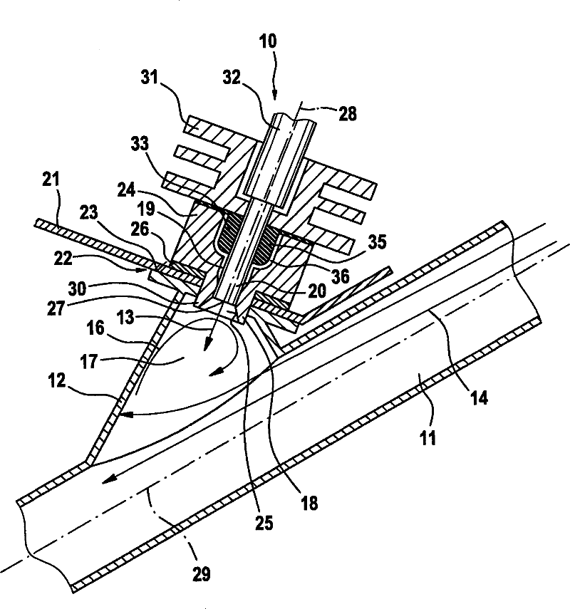
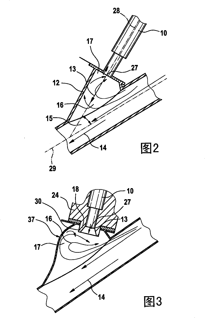
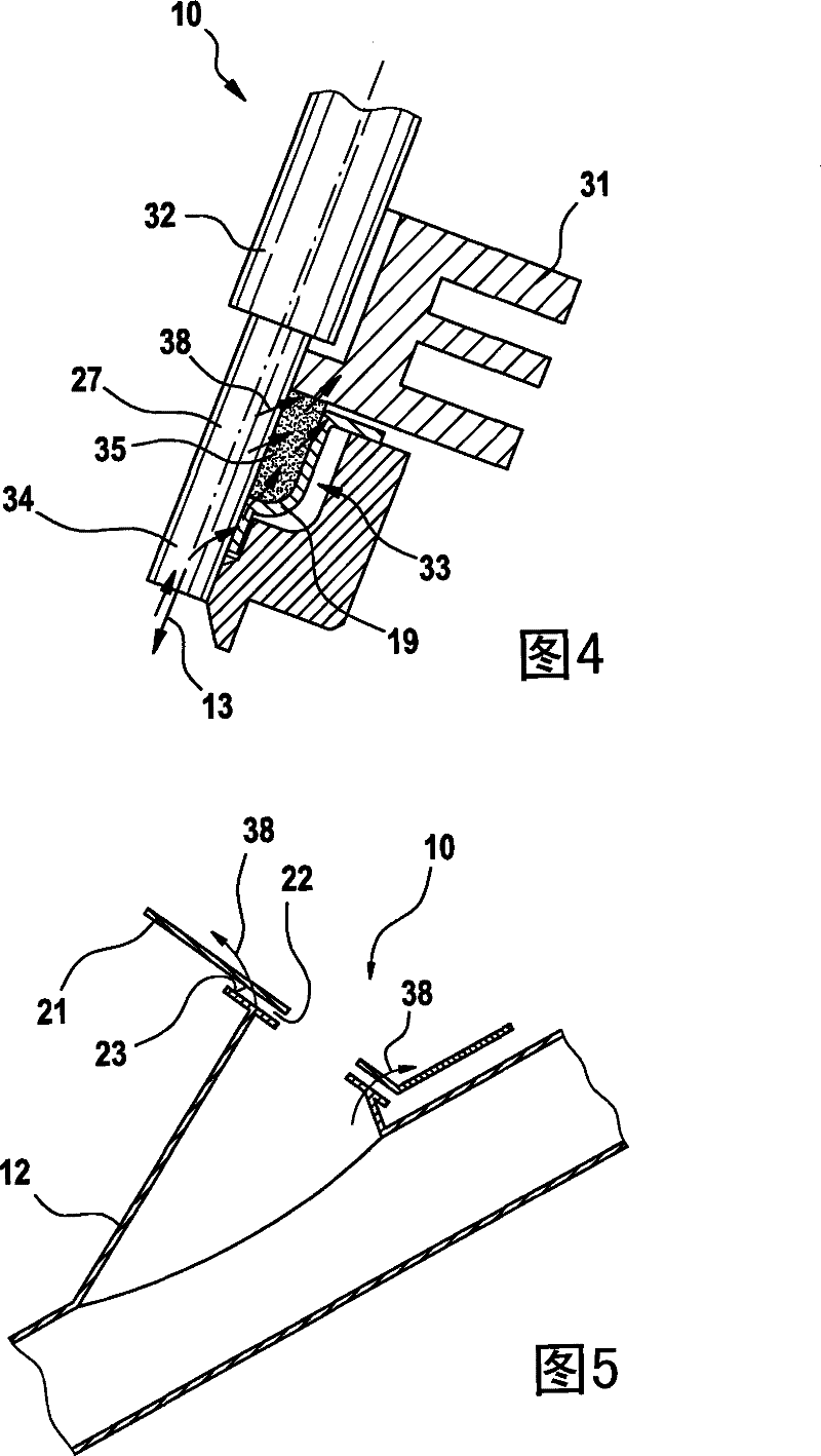
[0021] figure 1 A preferred embodiment of an exhaust gas aftertreatment device according to the invention for aftertreatment of exhaust gases in an exhaust system of an internal combustion engine is shown in a schematic sectional view, in which A catalytic converter (not shown) is provided for reducing the NOx fraction of the exhaust gas of the internal combustion engine. figure 2 , Figure 4 , Figure 5 and Figure 6 Each shows figure 1 detail view of the . image 3 An alternative embodiment of the flange 12 is shown. Like elements are numbered likewise in each of these figures.

[0022] The reducing agent is introduced into the exhaust pipe 11 along the inflow direction 13 via the valve tip 27 of the metering valve 10 . In the exhaust pipe 11 , the hot exhaust gas flow flows in the exhaust gas flow direction 14 . The exhaust line 11 is designed in such a way that less heat is introduced directly into the metering valve 10 and / or more heat can be discharged from the ...


PUM


Abstract

An automotive exhaust system has an exhaust pipe (11) with a reduction agent inlet with dosing valve (10) upstream from a NOx selective catalytic reduction converter. In the vicinity of the valve, the exhaust pipe is shaped to minimize the direct release of heat to the valve, and / or to facilitate the direct release of heat to the valve.

Description

technical field [0001] The invention relates to an exhaust gas aftertreatment device. Background technique [0002] In order to reduce the nitrogen oxides contained in the exhaust gases of internal combustion engines, methods for selective catalytic reduction ("SCR") have proven advantageous for internal combustion engines operating with excess air. In this method, nitrogen oxides are converted together with ammonia into nitrogen and water in a selective catalyst. The reducing agent required for the catalytic conversion of nitrogen oxides is carried in the vehicle instead of ammonia in the form of an aqueous urea solution, from which ammonia can be released in the amount required for the corresponding conversion by pyrolysis and hydrolysis of the urea solution. The aqueous urea solution is introduced into the reduction catalytic converter via a metering device, in particular a metering valve, via the exhaust pipe. The exhaust gas can have a very high temperature, which can...

Claims


Application Information

Patent Timeline
Patent Type & Authority Patents(China)
IPC IPC(8): F01N13/08F01N3/20
CPCF01N13/08F01N3/2066F01N2260/022F01N2610/1453F01N2260/20Y02T10/24F01N2610/11F01N2610/02Y02T10/12F01N3/02F01N3/20
Inventor R·黑贝雷尔M·比格林B·哈格尔C-A·科克利奇E·施奈德
Owner ROBERT BOSCH GMBH
Why Eureka
Try Eureka