Pile bottom post-grouting method

A post-grouting and pile bottom technology, which is applied to sheet pile walls, buildings, and foundation structure engineering, can solve problems such as unsatisfactory construction effects, and achieve the effects of improving grouting effects, bearing capacity, and boundary conditions

Inactive Publication Date: 2009-01-21
JIANGSU NANTONG NO 2 CONSTR ENG GRP
View PDF0 Cites 3 Cited by
  • Summary
  • Abstract
  • Description
  • Claims
  • Application Information

AI Technical Summary

Problems solved by technology

[0002] The post-pile grouting process was first used in some soft soil foundation areas such as Shanghai, but the construction effect has not been ideal, and the general grouting success rate is about 60%.

Method used


Image

  • Pile bottom post-grouting method
  • Pile bottom post-grouting method

Examples


Embodiment Construction

[0015] A post-grouting method at the bottom of a pile, comprising the following steps:

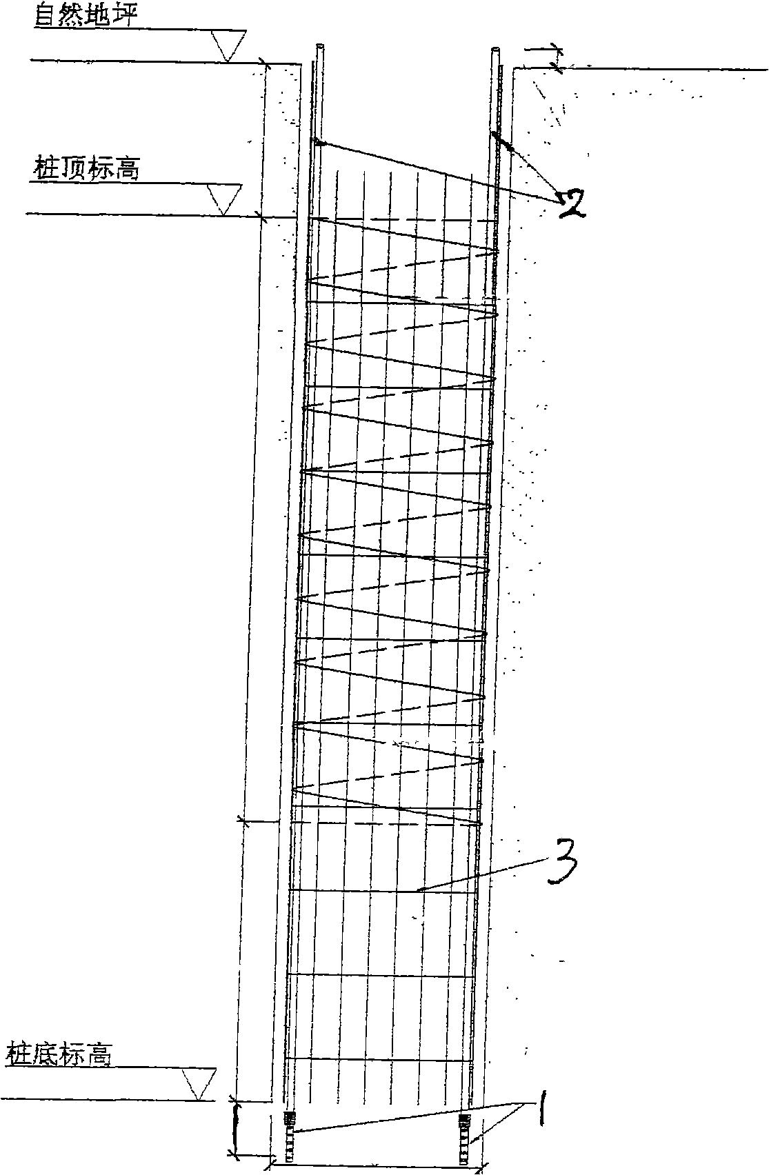
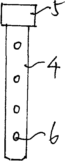
[0016] (1) During the construction of the bored pile, the grouting pipeline is preset at the bottom of the pile: the grouting device 1 is fixedly connected with the grouting pipe 2, the grouting pipe 2 is placed in the steel cage 3, and the iron wire is connected with the grouting pipe 2. The reinforcement cages are tied together and lowered together with the reinforcement cages. The grouting device extends 0.4 to 0.8 cm from the bottom of the reinforcement cage, and the grouting device is inserted into the pile bottom sediment and void soil to ensure the smooth flow of the grouting pipeline; The grouter includes a grouter pipe 4 (using steel pipe or high-strength PVC pipe, etc.), the feed end of the grouter pipe is equipped with a one-way valve 5 connected to the grouting pipeline, and the outer circumference of the grouter pipe wall is provided with multiple Pulp hole 6;

[0017] (2) Gr...


PUM


Abstract

The invention discloses a method for post-grouting in the bottom of a pile, which comprises the following steps: in the process of constructing the pile by drilling holes, a grouting pipeline is prearranged in the bottom of the pile and grout is injected. The method has good grouting effect and high success rate of grouting.

Description

Technical field: [0001] The invention relates to a post-grouting method for bored cast-in-place piles. Background technique: [0002] Post-pile grouting technology was first used in some soft soil foundation areas such as Shanghai, but its construction effect has been unsatisfactory, and the general grouting success rate is about 60%. Invention content: [0003] The purpose of the present invention is to provide a post-grouting method at the pile bottom with good grouting effect and high grouting success rate. [0004] Technical solution of the present invention is: [0005] A post-grouting method at the bottom of a pile is characterized in that it comprises the following steps: [0006] (1) During the construction of the bored pile, the grouting pipeline is preset at the bottom of the pile: the grouting device is fixedly connected with the grouting pipe, the grouting pipe is placed in the steel cage, and the steel wire is tied to the steel cage Together, it is lowered ...

Claims


Application Information

Patent Timeline
Patent Type & Authority Applications(China)
IPC IPC(8): E02D5/34
Inventor 张建平黄应仲胡勇俞雷
Owner JIANGSU NANTONG NO 2 CONSTR ENG GRP
Why Eureka
Try Eureka