Membrane structure ceiling tension device
A technology of tensioning device and membrane structure, applied in the direction of ceiling, building components, building structure, etc., can solve the problems of inconvenient use, complex structure, high cost, etc., and achieve the effect of convenient adjustment, low cost and low cost
- Summary
- Abstract
- Description
- Claims
- Application Information
AI Technical Summary
Problems solved by technology
Method used
Image
Examples
Embodiment 1
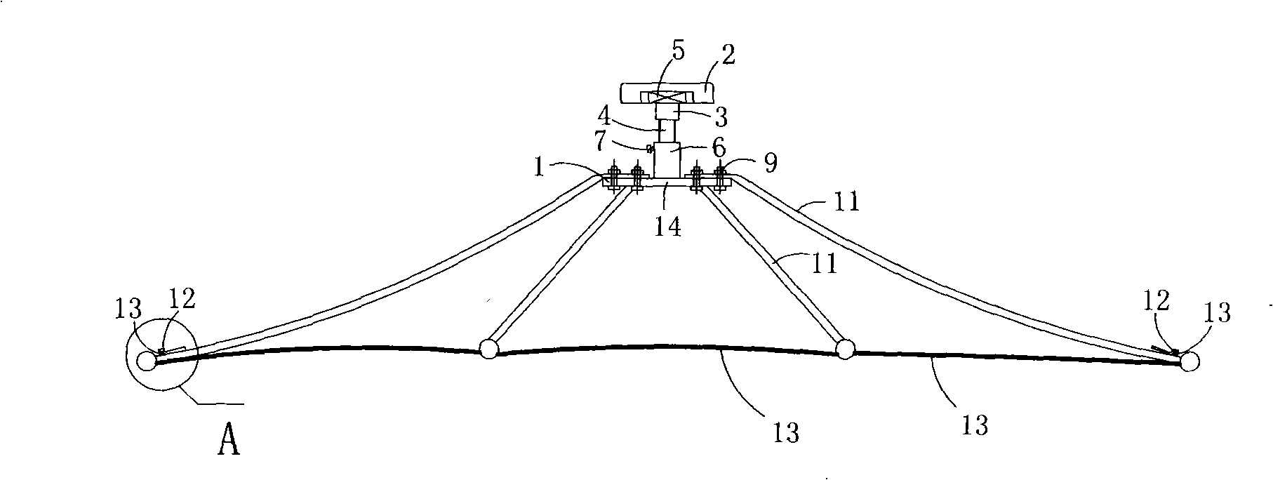
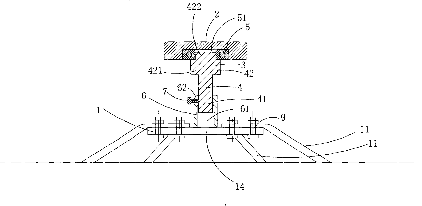
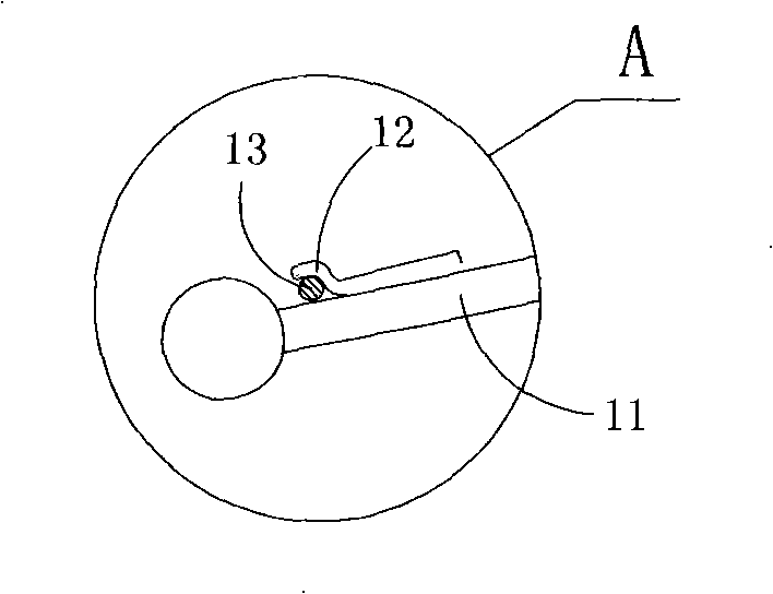
[0025] Figure 1 to Figure 3 A specific embodiment of the invention is shown in which, figure 1 It is a structural schematic diagram of the present invention, figure 2 Yes figure 1 The partial cross-sectional structure schematic diagram of the membrane structure roof tensioning device shown; image 3 Yes figure 1 The partial enlarged schematic diagram of A.
[0026] This embodiment is a membrane structure ceiling tensioning device, see Figure 1 to Figure 3 , comprising a base frame 1, a tensioning element 2 positioned above the base frame 1, and an adjusting device 3 for adjusting the distance between the tensioning element 2 and the base frame 1; The positioning tube 6, the adjusting column 4 that can reciprocate in the cavity 61 of the positioning tube 6 with its own rotation, the bearing 5 that is driven by the adjusting column 4 to rotate, and the shaft for blocking the rotation of the adjusting column 4 The locking screw 7 ; the lower part 41 of the adjusting colu...
Embodiment 2
[0033] Image 6 It is a schematic cross-sectional view of the second structure of the present invention, showing the second embodiment of the present invention.
[0034] This embodiment is basically the same as Embodiment 1, except that the adjustment device 3 further includes a nut 43 matched with the adjustment column 4, and the nut 43 is sleeved on the adjustment column 4 .
[0035] In this embodiment, when the ceiling of the external membrane structure needs to be tensioned, the nut can be screwed upwards to the bottom of the support part of the adjustment column first, and at this time, the nut can be rotated forward to drive the adjustment column to rotate , so that the adjusting column can move upward in the hole 61 of the positioning tube 6 with its own rotation, thereby increasing the distance between the tensioning element 2 and the base frame 1, and tensioning the ceiling of the external membrane structure. Thereafter, the nut can be reversely screwed down to the ...
Embodiment 3
[0037] Figure 7 It is a schematic cross-sectional view of the third structure of the present invention; showing the third embodiment of the present invention.
[0038] This embodiment is basically the same as Embodiment 1, the difference is that: the adjustment device 3 also includes two nuts 43 matched with the adjustment column 4, and the two nuts 43 are sleeved on the Adjust column 4. In addition, the locking screw 7 is omitted in this embodiment, and the screw hole 62 matching the locking screw 7 is no longer provided on the tube wall of the positioning tube 6 .
[0039] In this embodiment, when the roof of the externally connected membrane structure needs to be tensioned, one of the lower nuts can be screwed upwards to the bottom of the upper nut, and at this time, the lower nut can be rotated forward to drive the The adjustment column rotates, so that the adjustment column can move upward in the cavity 61 of the positioning tube 6 with its own rotation, thereby increa...
PUM
 Abstract
Description
Claims
Application Information
 - R&D
- Intellectual Property
- Life Sciences
- Materials
- Tech Scout
- Unparalleled Data Quality
- Higher Quality Content
- 60% Fewer Hallucinations
Browse by: Latest US Patents, China's latest patents, Technical Efficacy Thesaurus, Application Domain, Technology Topic, Popular Technical Reports.
© 2025 PatSnap. All rights reserved.Legal|Privacy policy|Modern Slavery Act Transparency Statement|Sitemap|About US| Contact US: help@patsnap.com


