Plate-to-plate concentration mounting type RF coaxial connector

A radio frequency coaxial, board-to-board technology, applied in the direction of connection, two-part connection device, coupling device, etc., can solve the problems of inconvenient processing, aggravated wear, damage to coaxial connectors, etc., to facilitate manufacturing and use, and save operation. time, reducing the effect of plugging and unplugging

Active Publication Date: 2009-01-21
宁波吉品科技有限公司
View PDF1 Cites 41 Cited by
  • Summary
  • Abstract
  • Description
  • Claims
  • Application Information

AI Technical Summary

Problems solved by technology

However, after careful analysis of the structure of the above-mentioned coaxial connector, it is found that: (1) The flanges at both ends of the outer conductor of the male connector have the same structure, and they are all inserted directly into the opening of the corresponding female connector shell. The locking between the connectors is realized by the cooperation between the curved inner cavity of the insulator and the spherical surface of the insulator, but due to the influence of the insulating material, it is easy to wear between the curved inner cavity of the insulator and the spherical surface of the insulator. The connector will be damaged under the number of mating times, that is, its service life is short
(2) Since the insulators and insulators of the female and male connectors need to be proces...

Method used


Image

  • Plate-to-plate concentration mounting type RF coaxial connector
  • Plate-to-plate concentration mounting type RF coaxial connector
  • Plate-to-plate concentration mounting type RF coaxial connector

Examples


Embodiment Construction

[0022] The present invention will be further described in detail below in conjunction with the accompanying drawings and embodiments.

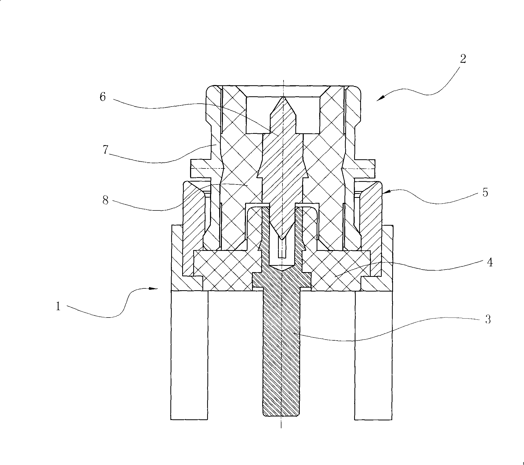
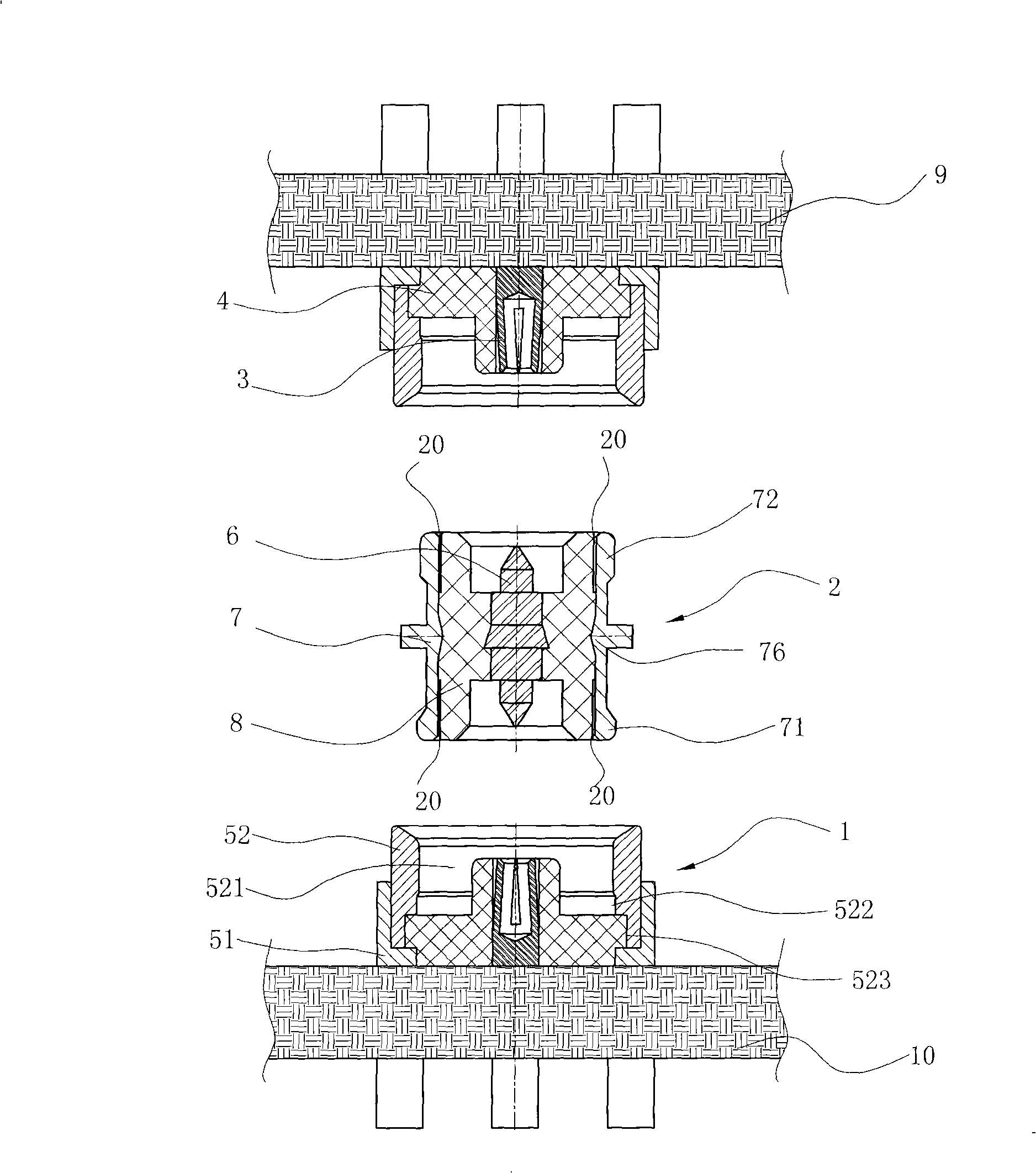
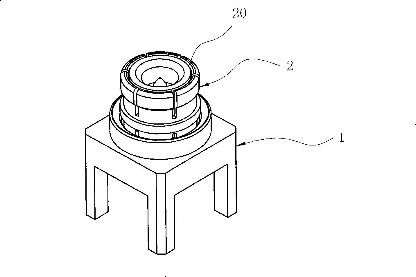
[0023] Such as Figure 1 to Figure 8 As shown, the radio frequency coaxial connector is composed of two sockets 1 and an adapter 2 between the two sockets, wherein the two sockets have the same structure and are installed on the upper circuit board 9 and the lower circuit board 10 respectively, and each socket 1 has a The electrical conductor 3 with socket, the insulator 4 and the socket shell 5 assembled in sequence from inside to outside, in this embodiment, the socket shell 5 adopts a split structure, that is, it is composed of a seat body 51 and a cylinder body 52, and the seat body 51 has a Four mounting feet 512, so as to be fixed on the circuit board, see image 3 As shown in Fig. 5, there is a stepped hole 511 in the middle of the base body; and one end of the cylinder 52 is seated in the above-mentioned stepped hole, and a limiting g...


PUM

PropertyMeasurementUnit
Gapaaaaaaaaaa
Gapaaaaaaaaaa

Abstract

The invention discloses a plate-to-plate intensive assemblage coaxial connector, comprising two sockets and a commutator. A first flange and a second flange with different axial lengths are arranged on the peripheral planes of the two ends of the commutator; a groove is arranged on the side wall at the bottom of the opening of the socket; when the commutator is inserted into the socket, the first flange is located in the groove, the second flange clings to the inner side wall of the corresponding socket opening. Because the first flange, the second flange and the groove matching the first flange are provided, the plugging and pulling forces become varied, the commutator is left on one of the circuit boards when being pulled away, thereby, the operation time is saved and ineffective plugging and pulling actions reduced; in addition, the lockup between the shells is used to largely increase the plugging and adapting frequency. By taking advantage of the clearance between the commutator shell and the insulator thereof, the commutator deviates in the opening upon incorrect medium condition, as a result, the position is corrected automatically and the purpose of direct plugging and adapting is achieved.

Description

technical field [0001] The invention relates to a coaxial connector, in particular to a high-density mounting type radio frequency coaxial connector applied between printed circuit boards. Background technique [0002] At present, with the development of communication technology, the volume of various military and civilian microwave communications, mobile communications and precision testing instruments tends to be miniaturized and miniaturized. For this reason, higher requirements are put forward for the coaxial connectors used in these devices, especially the high-density mounted radio frequency coaxial connectors between circuit boards. [0003] A general coaxial connector is composed of a plug male connector (abbreviated as a plug) and a socket female connector (abbreviated as a socket). Most of the existing common coaxial connectors use threaded connectors or quick-plug connectors. Among them, the threaded connector is to connect the screw sleeve by screwing, so that i...

Claims


Application Information

Patent Timeline
IPC IPC(8): H01R24/02H01R31/06H01R24/40
Inventor 尹仕方人根詹昌吉
Owner 宁波吉品科技有限公司
Why Eureka
Try Eureka