Modular fixed and mobile bearing prosthesis system

一种假体、骨承座的技术,应用在假体、医药科学、膝关节等方向

Active Publication Date: 2009-01-21
DEPUY PROD INC
View PDF2 Cites 15 Cited by
  • Summary
  • Abstract
  • Description
  • Claims
  • Application Information

AI Technical Summary

Problems solved by technology

This may occur if the surgeon observes extensive joint space narrowing on x-ray during revision surgery

Method used


Image

  • Modular fixed and mobile bearing prosthesis system
  • Modular fixed and mobile bearing prosthesis system
  • Modular fixed and mobile bearing prosthesis system

Examples


Embodiment Construction

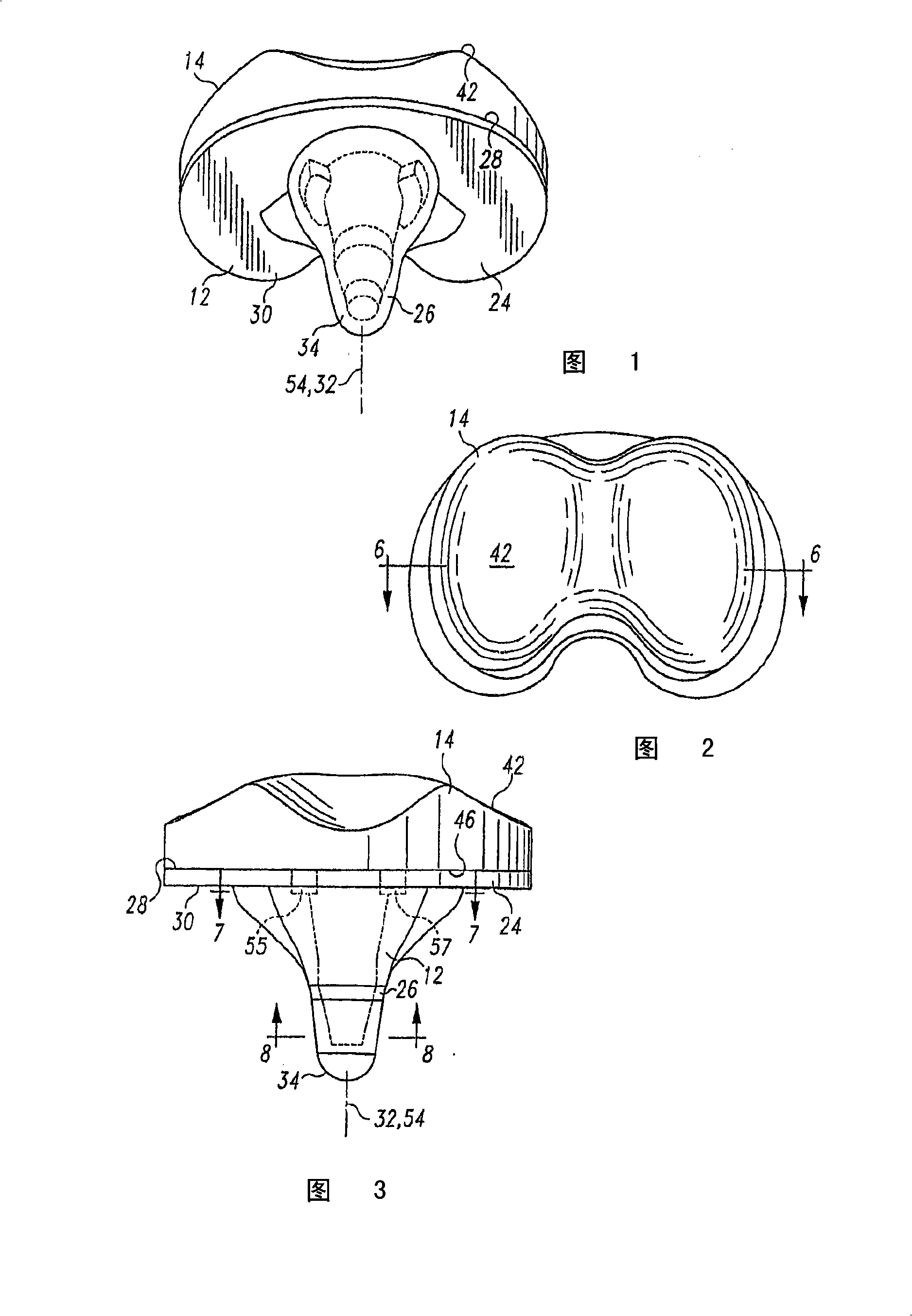
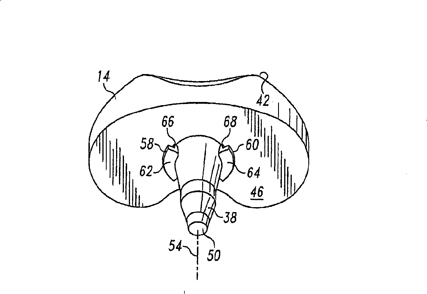
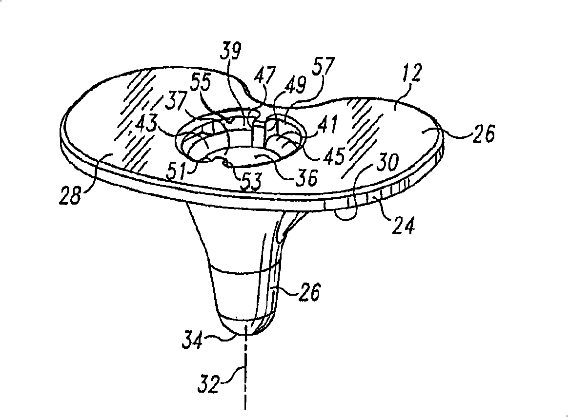
[0033] The present invention provides a prosthetic knee system comprising a femoral implant component 10 (such as Figure 13 shown), a shared tibial base component 12 (as shown in Figures 1-3, 5-8, and 10-12), and interchangeable socket components 14, 16 that can be They are selectively assembled with the common tibial base component 12 respectively. The first bearing part 14 is a fixed bearing part; the second bearing part 16 is a movable bearing part.

[0034] Figure 13 The illustrated femoral component 10 includes two raised seating surfaces 18 , 20 . Femoral component 10 may be fabricated from standard materials such as cobalt-chromium or titanium alloys and may include standard features for such femoral implants. For example, the bone-facing portion 22 may be porous to allow bone ingrowth or may have recesses to enhance cement fixation. The present invention is not limited to any particular type of femoral component or to any particular feature unless expressly state...


PUM


Abstract

The present invention relates to a modular fixed and mobile bearing prosthesis system. A knee prosthetic system includes a femoral component, a fixed tibial bearing component, a mobile tibial bearing component and an integrated or common tibial base component. The same tibial base component can be used with either the fixed tibial bearing component or the mobile tibial bearing component. The fixed bearing component and tibial base component have mating anti-rotation features. One embodiment of the mobile bearing component does not engage the anti-rotation feature of the tibial base component. Another embodiment engages the anti-rotation feature to allow for limited rotation.

Description

[0001] Cross References to Related Applications [0002] Priority is claimed from application Serial No. 60 / 732,000, entitled "Modular Fixed and Removable Bearing Prosthesis System," filed October 31, 2005, by Adam I. Hayden and Luke J. Aram U.S. Provisional Patent Application (Docket No. DEP5602USPSP). technical field [0003] The present invention generally relates to prostheses for human joints, and in particular, the present invention relates to prostheses for human knees. Background technique [0004] When a person's bone joints have been damaged by accident or disease, it may be necessary to replace the damaged joint with a prosthesis in order to relieve pain and restore the joint to normal use. The entire joint is usually replaced by a surgical procedure that involves removing the ends of the corresponding damaged bone and replacing these ends with a prosthetic implant. This procedure of replacing the native joint with a prosthetic joint is called primary total join...

Claims


Application Information

Patent Timeline
Patent Type & Authority Applications(China)
IPC IPC(8): A61F2/64
CPCA61F2/389A61F2002/30604A61F2002/30329A61F2220/0025A61F2002/30614A61F2220/0033A61F2002/30336A61F2002/30616A61F2/3868
Inventor L·阿拉姆A·海登
Owner DEPUY PROD INC
Why Eureka
Try Eureka