Hybrid drive device

A hybrid drive and clutch technology, applied in power units, transmissions, gear transmissions, etc., can solve the problems of large shape, high cost, heavy weight, etc., and achieve the effect of reducing impact

Inactive Publication Date: 2009-01-21
AISIN AW CO LTD
View PDF1 Cites 14 Cited by
  • Summary
  • Abstract
  • Description
  • Claims
  • Application Information

AI Technical Summary

Problems solved by technology

However, the rotating electrical machine with larger output torque has the disadvantages of large shape, heavy weight, and high cost.

Method used


Image

  • Hybrid drive device
  • Hybrid drive device
  • Hybrid drive device

Examples


no. 2 Embodiment approach

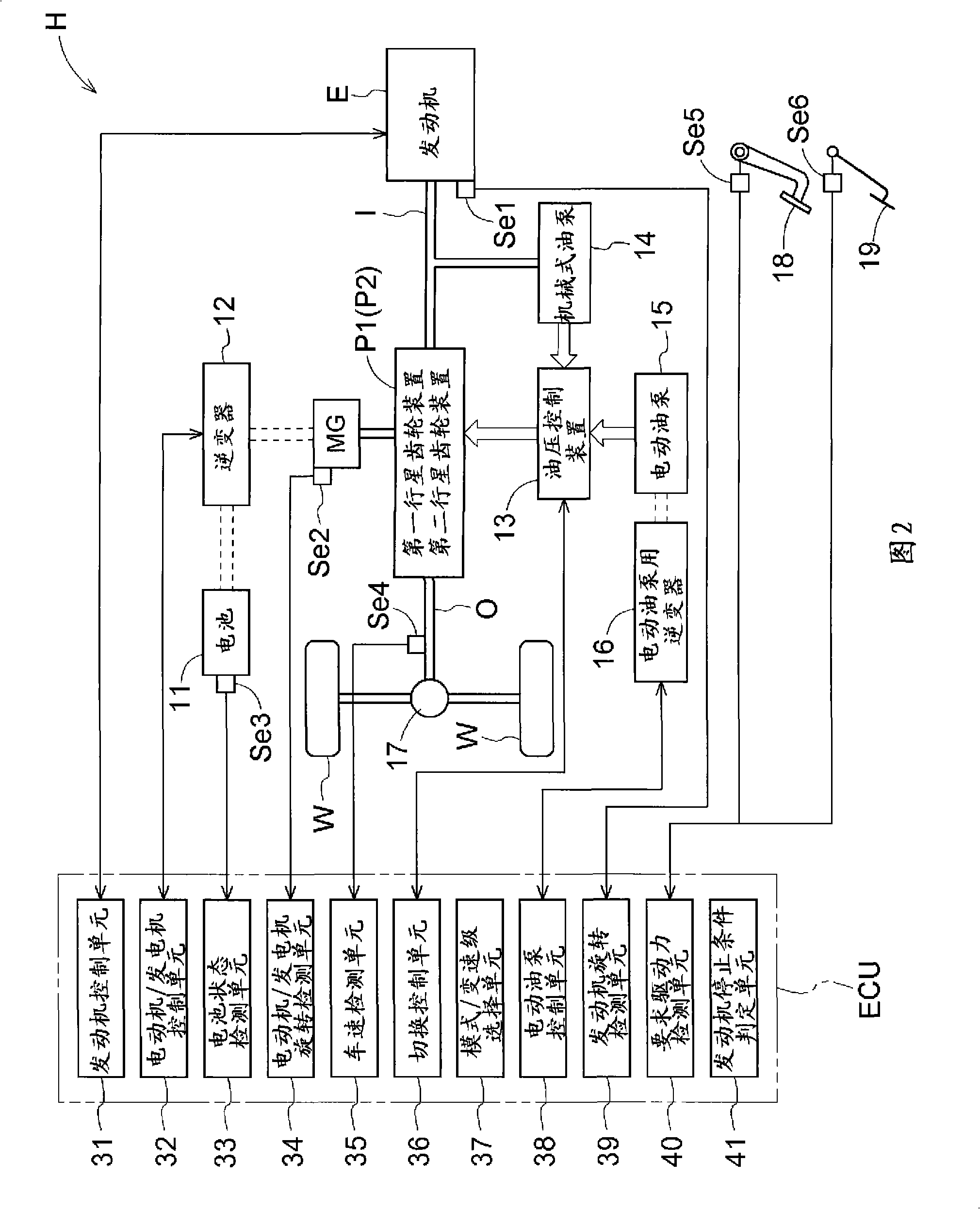
[0144] Next, a second embodiment of the present invention will be described. The hybrid drive device H according to the present embodiment has a configuration similar to that of the hybrid drive device H according to the above-described first embodiment, but has a configuration in which the parallel mode and the electric driving mode are further multi-staged, that is, in the parallel mode The lower includes the reverse stage, with 7 gear shifts, and in electric drive mode, with 3 shifts. Hereinafter, the hybrid drive device H according to the present embodiment will be described focusing on the differences from the above-described first embodiment. In addition, the system configuration of the hybrid drive device H according to the present embodiment is the same as that in FIG. 2 , and therefore, the description of this point is omitted. In addition, other structures are the same as those of the above-mentioned first embodiment unless otherwise specified.

[0145] 2-1. Config...

no. 3 Embodiment approach

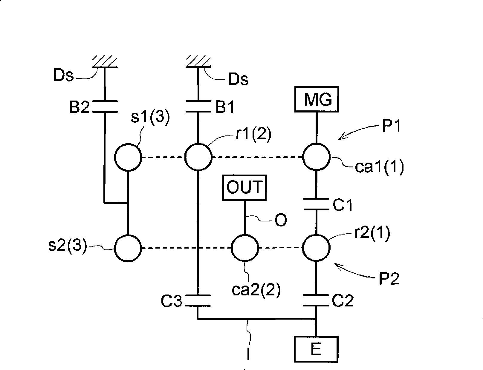
[0179] Next, a third embodiment of the present invention will be described. The hybrid drive device H according to the present embodiment is configured to integrally rotate the carrier ca1, which is the “second rotation member” of the first planetary gear device P1, and the carrier ca2, which is the “third rotation member” of the second planetary gear device P2. The ring gear r1, which is the "third rotating member" of the first planetary gear device P1, is selectively fixed to the case Ds by the first brake B1. This point is the same as the configuration of the first embodiment described above, that is, the "third rotating element (3) (sun gear s1)" of the first planetary gear device P1 and the "third rotating element (3) (sun gear s1)" of the second planetary gear device P2 The sun gear s2)" is integrally rotatably connected, and the "second rotation element (2) (ring gear r1)" of the first planetary gear device P1 is selectively fixed to the case Ds by the first brake B1. ...


PUM


Abstract

A hybrid drive device can take a state functioning as an electric torque converter and capable of transmitting a large torque to an output shaft side even when a rotating electric machine with a relatively small output torque is used. The hybrid drive device (H) comprises an input shaft (I) connected to an engine (E), an output shaft (O) connected to a wheel, a motor generator (MG), a first planetary gear device (P1), and a second planetary gear device (P2). In the electric torque converter mode, the first planetary gear device (P1) reduces the absolute value of the rotational speed of the motor generator (MG) and transmits the reduced absolute value to the second planetary gear device (P2), and the second planetary gear device (P2) combines the rotation transmitted from the first planetary gear device (P1) with the rotation of the input shaft (I), reduces the absolute value of the rotational speed of the input shaft (I), and transmits the reduced absolute value to the output shaft (O).

Description

technical field [0001] The present invention relates to a hybrid drive having an input shaft connected to an engine, an output shaft connected to wheels, a rotary electric machine, a first planetary gear unit, a second planetary gear unit, and an electrical torque converter as an electrical torque converter. state of functioning. Background technique [0002] Regarding the hybrid drive device in a state of functioning as an electric torque converter, for example, Patent Document 1 described below has a configuration as shown in FIG. 42 . This hybrid drive device includes an input shaft I connected to the engine, an output shaft O connected to the wheels, a first rotary electric machine M1, a second rotary electric machine M2, a power split mechanism SP having a double planetary gear device PG, and An automatic transmission AT is connected in series between the power split mechanism SP and the output shaft O via a transmission member T. Here, the planetary gear device PG in...

Claims


Application Information

Patent Timeline
Patent Type & Authority Applications(China)
IPC IPC(8): B60K6/20B60K17/04B60L11/14F16H3/62F16H3/72B60L50/16
CPCF16H2200/2023F16H2200/2046B60W10/115F16H2037/0886B60K6/387B60K6/48B60W10/02B60K6/547B60K6/365B60W20/00F16H2200/2043F16H2200/2007F16H3/728F16H2200/2048F16H3/725B60K6/40B60W10/08Y02T10/6221B60L15/20B60L15/2054B60L2240/12B60L2240/14B60L2240/421B60L2240/423B60L2240/441B60L2240/443B60L2240/486B60L2240/507B60L2250/26B60L2260/26B60L2270/145B60L50/16B60L58/12Y02T10/62Y02T10/64Y02T10/70Y02T10/7072Y02T10/72B60W20/40
Inventor 岩中诚高见重树
Owner AISIN AW CO LTD
Why Eureka
Try Eureka