Machine for stringing chain-sheets

The technology of a stringer and chain piece is applied in the field of chain manufacturing equipment, which can solve the problems of slow stringing speed, inability to carry out oil film, wet film stringing operation, low production efficiency, etc., and achieves improved reliability and is conducive to stringing The effect of film speed

Inactive Publication Date: 2009-01-28
郦忠
View PDF3 Cites 17 Cited by
  • Summary
  • Abstract
  • Description
  • Claims
  • Application Information

AI Technical Summary

Problems solved by technology

One is that the structure of the whole machine is loose, and the mechanism setting is not compact and unreasonable in the links from chain piece conveying, sorting, sorting to discharging, which leads to poor operation reliability; secondly, the speed of stringing pieces is slow and the production efficiency is low; thirdly, it is only suitable for Dry film operation, oil film and wet film serial operations are not allowed

Method used


Image

  • Machine for stringing chain-sheets
  • Machine for stringing chain-sheets
  • Machine for stringing chain-sheets

Examples


Embodiment Construction

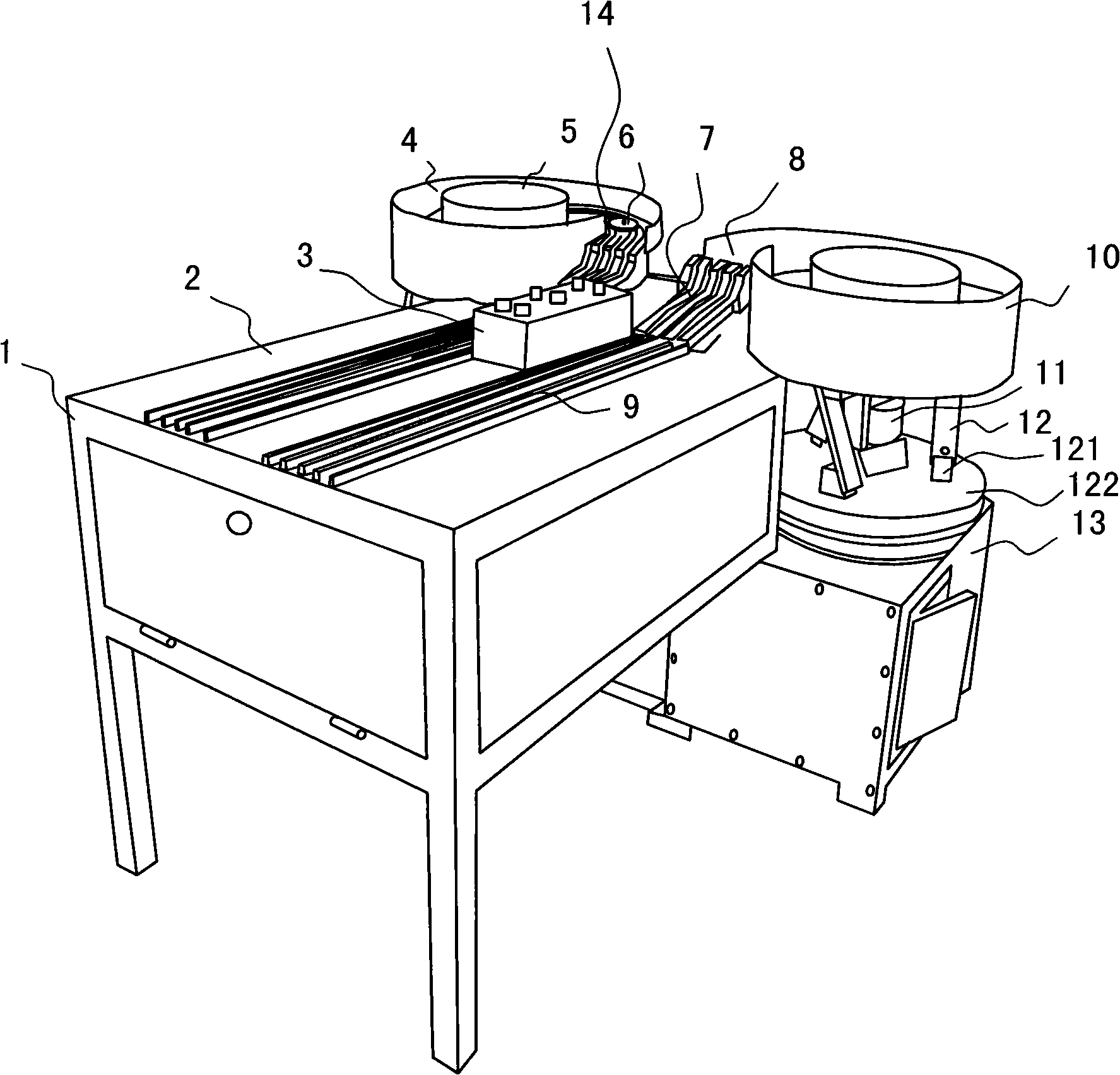
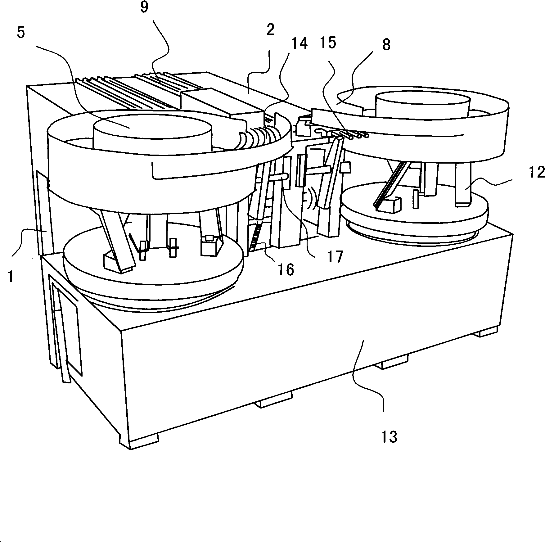
[0021] see figure 1 , and combined with figure 2 . This is a machine that has the function of connecting the inner and outer chains of the chain. Therefore, two sets of chaining mechanisms are symmetrically set on the frame 1. The chain piece needs to be set, corresponding to the difference in parameters such as the size, shape and thickness of the inner chain piece and the outer chain piece.

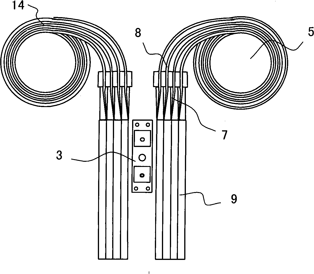
[0022] Frame 1 front portion is provided with worktop 2, and rear portion is provided with hopper 5, and motor, transmission mechanism are housed in transmission mechanism box 13, certainly, on frame 1, some accessory structures such as toolboxes can be set as required, to facilitate work. There is a discharge chute 9 and an electric control box 3 on the work surface 2, and the electric control box 3 is arranged on the symmetrical middle part of the work surface 2, which is convenient for the operation of the left and right stations.

[0023] As far as a single stringing mechanism i...


PUM


Abstract

A link plate stringing machine comprises a frame, a hopper, a feeding tank, a monolith tank, a discharge tank and a pushing device, wherein, the hopper takes the shape of a cylinder, the feeding tank is arranged on the periphery of the hopper and integrated with the cylinder body. The monolith is arranged on a vibrating bracket; an discharge outlet of the hopper is communicated with the feeding tank, a plurality of gradually rising spiral feeding rails are arranged in the feeding tank, and clearance is kept between the feeding rails; the monolith tank is composed of a plurality of monolith rails, a step is respectively formed at inlets of the monolith rails and outlets of the corresponding feeding rails, the monolith rail behind the step takes the shape of a tunnel, and the wall of the monolith rail in the shape of the tunnel is provided with gaps in the axial direction; the monolith rails are respectively provided with a pushing rod hole for accommodating the pushing device, the outlets of the monolith rails are butt-jointed with the inlet of the discharge tank. By adopting the link plate stringing working procedure on the frame, the link plate stringing machine has the advantages of solving the existing defects of loose mechanical structure, bad reliability, slow strip stringing speed, low production efficiency and only being applicable to dry strip stringing work.

Description

【Technical field】 [0001] The invention relates to a chain manufacturing equipment, in particular to a chain chain machine. 【Background technique】 [0002] In order to improve production efficiency, reduce labor intensity, and change the long-term status quo of manual stringing of chains, technicians have made unremitting efforts and effective explorations for many years, and have successively designed various forms of chaining machines. Patent No. 200520012869.4 "A chain plate alignment device for chain plate stringer", 200520102509.3 "A chain plate stringer", 96216327.9 "Chain plate automatic stringer" all involve this kind of machinery or this Related institutions in class machinery. The structure of this type of machinery usually includes a frame, a hopper, a slide plate behind the outlet of the hopper, a monolithic chute and a chute, and the pushing device is matched with the monolithic chute. The slide plate is also provided with a material shifting roller, the bottom...

Claims


Application Information

Patent Timeline
Patent Type & Authority Applications(China)
IPC IPC(8): B21L9/06
Inventor 郦均郦忠郦丰
Owner 郦忠
Why Eureka
Try Eureka