
Automobile sensor with bus interface
A bus interface and sensor technology, applied in the field of sensors, can solve the problems of large space occupation, high cost of wiring harness, complicated wire connection in the car, etc., and achieve the effect of space saving, simple control and optimization of wiring harness
- Summary
- Abstract
- Description
- Claims
- Application Information
AI Technical Summary
Problems solved by technology
Method used
Image

Examples
Embodiment Construction
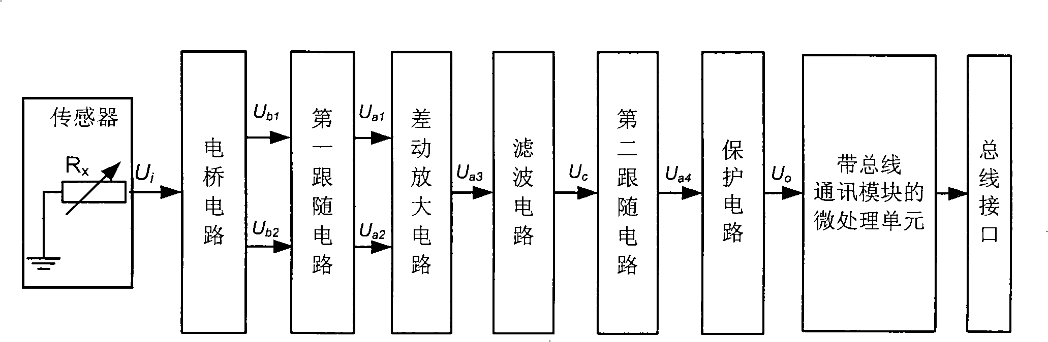
[0022] The sensor with a bus interface for automobiles proposed by the present invention has a circuit block diagram such as figure 1 Shown, including:
[0023] Sensor, used to convert the measured physical signal into a resistance signal, and the resistance signal U i Output to the bridge circuit, the sensor is a variable resistor R x One end of the variable resistor is connected to the ground signal, and the other end is connected to the bridge circuit. During operation, its resistance value changes with the change of the measured signal.
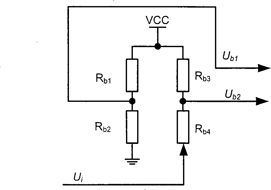
[0024] Bridge circuit, used to receive the output signal U of the variable resistance sensor i , Produce differential signal U b1 And U b2 And output to the first follower circuit. The circuit principle of the bridge circuit is as figure 2 As shown, there are four resistors R b1 , R b2 , R b3 , R b4 Composition, connected by electric bridge. Resistance R b1 One end is connected to the digital electric signal Vcc, one end is connected to R b...
PUM
 Abstract
Description
Claims
Application Information