Wiring harness, vehicle component, mold, mold system and method for manufacturing the wiring harness

a manufacturing method and technology for wiring harnesses, applied in the direction of insulated conductors, cables, conductors, etc., can solve the problem of particularly expensive production of wiring harnesses

Active Publication Date: 2021-12-07
YAZAKI SYST TECH
View PDF24 Cites 0 Cited by
  • Summary
  • Abstract
  • Description
  • Claims
  • Application Information

AI Technical Summary

Benefits of technology

[0006]It was recognized that an improved wiring harness for a motor vehicle can be provided if the wiring harness has a cable bundle with at least two cables and an envelope. At least some section or sections of the cable bundle is / are embedded in the envelope. In this way, it is possible to dispense with laborious winding of the cable bundle. Moreover, the envelope ensures that the wiring harness can be bent and guided around tight radii particularly easily. Moreover, the individual cables of the cable bundle are protected by the envelope.
[0049]In another embodiment, the material of the envelope is applied in a manner fluctuating in an undulating fashion in the transverse direction with respect to the cable bundle between the first wall section and the second wall section. In this way, reliable embedding of the cable bundle in the surrounding wall is ensured.

Problems solved by technology

The wiring harness is produced substantially in a manual way, and therefore the production of the wiring harness is particularly expensive.

Method used


Image

  • Wiring harness, vehicle component, mold, mold system and method for manufacturing the wiring harness
  • Wiring harness, vehicle component, mold, mold system and method for manufacturing the wiring harness
  • Wiring harness, vehicle component, mold, mold system and method for manufacturing the wiring harness

Examples


first embodiment

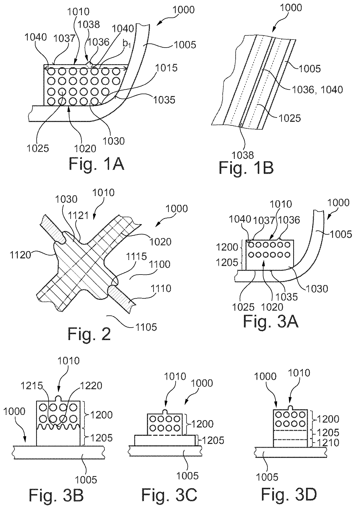
[0092]FIG. 1A shows a detail of a cross section through a vehicle component 1000 of a motor vehicle according to a The vehicle component 1000 has a structure 1005 and a wiring harness 1010. The structure 1005 can be a body, a deep-drawn part, a roof lining, a door panel, an intermediate panel, a soundproofing bulkhead or a cockpit, for example. The structure 1005 can be manufactured from sheet metal or plastic, for example. However, the structure 1005 can also be a plastic structure, a carpet or similar. The structure 1005 has a bearing surface 1015. The bearing surface 1015 faces the wiring harness 1010.

[0093]The wiring harness 1010 has a cable bundle 1020 comprising a plurality of cables 1025. The cables 1025 serve to transmit electric signals or an electric current between two points. The cables 1025 are arranged so as to run approximately in the same direction to one another. In this arrangement, a connecting system for connecting the wiring harness 1010 electrically to another...

second embodiment

[0099]FIG. 2 shows a section through a vehicle component 1000 according to a The vehicle component 1000 is configured in such a way as to be substantially identical to the vehicle component 1000 shown in FIG. 1A and FIG. 1B. The structure 1005 has a first space 1100 and a second space 1105. A partition wall 1110 is provided between the first space 1100 and the second space 1105. The partition wall 1110 has an opening 1115. The wiring harness 1010 is passed through the opening 1115.

[0100]The wiring harness 1010 is configured in such a way as to be substantially identical to the wiring harness 1010 illustrated in FIG. 1A and FIG. 1B. In addition, the envelope 1030 of the wiring harness 1010 has a second bulge 1120. The second bulge 1120 extends transversely to a longitudinal extent of the cable bundle 1020. At least in the region of the second bulge 1120, the envelope 1030 advantageously comprises a flexible material. The second bulge 1120 has a bulge contour 1121. The second bulge 1...

third embodiment

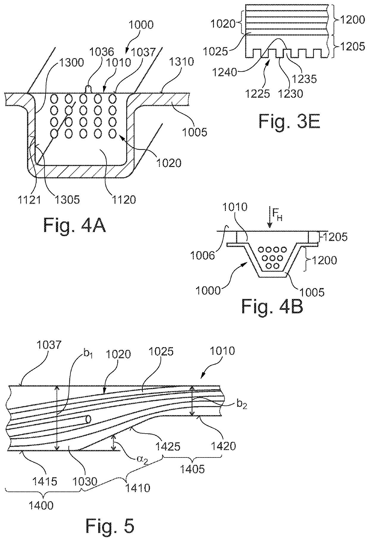
[0101]FIG. 3A shows a detail of a cross section through a vehicle component 1000 of the motor vehicle according to a The vehicle component is of similar configuration to the vehicle component 1000 shown in FIGS. 1 and 2. As a departure therefrom, the wiring harness 1010 has a first layer 1200 and a second layer 1205. The second layer 1205 is arranged below the first layer 1200 and between the first layer 1200 and the structure 1005. The cable bundle 1020 is embedded in the first layer 1200. In this arrangement, a first bulge 1036 adjoins the first layer 1200. The first layer 1200 preferably comprises a first material, and the second layer 1205 preferably comprises a second material. It is also possible for the first layer 1200 and the second layer 1205 to comprise an identical material. Here, the second material can have a different elasticity from the first material. Thus, it is advantageous, if the elasticity of the second material is greater than the elasticity of the first mate...


PUM

PropertyMeasurementUnit
angleaaaaaaaaaa
angleaaaaaaaaaa
angleaaaaaaaaaa

Abstract

The invention relates to a wiring harness (1010), a motor vehicle component (1000), a mold (15) for manufacturing a wiring harness (1010), a mold system (10) and a method for manufacturing the wiring harness (1010), the wiring harness (1010) comprising at least one bunch (1020) of at least two cables (1025) and a sheath (1030), at least some sections of the bunch (1020) of cables being embedded in the sheath (1030).

Description

CROSS-REFERENCE TO RELATED APPLICATION[0001]This application is a National Stage of International Application No. PCT / EP / 2017 / 061054, filed on May 9, 2017, which claims priority from German Patent Application No. 10 2016 108 522.7, filed on May 9, 2017.BACKGROUNDField of the Invention[0002]The invention relates to a wiring harness, to a vehicle component of a motor vehicle, to a mold for manufacturing a wiring harness, to a mold system and to a method for manufacturing the wiring harness.Background[0003]Wiring harnesses with individual cables for connecting different components in a motor vehicle are known. In this context, the cables are strung on a mounting board and wound in a winding tape. The wiring harness is produced substantially in a manual way, and therefore the production of the wiring harness is particularly expensive.[0004]It is the object of the invention to provide an improved wiring harness, an improved vehicle component, an improved mold, an improved mold system and...

Claims


Application Information

Patent Timeline
Patent Type & Authority Patents(United States)
IPC IPC(8): B60R16/02B29C45/14H01B7/00H01B7/36H01B13/012B29L31/34
CPCB60R16/0215B29C45/14065B29C45/14549B60R16/0207H01B7/0045H01B7/365H01B13/01209B29K2827/18B29K2859/00B29L2031/3462
Inventor EINERT, MARTINRODERER, GOTZNAVARRO MALAGA, ALDOVON KNORRE, DIETRICHNEAL, ADAM
Owner YAZAKI SYST TECH
Why Eureka
Try Eureka