Vehicle speed sensor with bus interface for vehicle

A vehicle speed sensor and bus interface technology, which is applied to devices using electric/magnetic methods, bus networks, data exchange through path configuration, etc., can solve the problems of high cost of wiring harness, large space occupation, and complicated connection of wires in the vehicle. , to achieve the effect of simple control, space saving and wiring harness optimization

Active Publication Date: 2010-06-02
TSINGHUA UNIV
View PDF2 Cites 0 Cited by
  • Summary
  • Abstract
  • Description
  • Claims
  • Application Information

AI Technical Summary

Problems solved by technology

[0002] In the traditional automobile body electrical system, the sensor output signal of the car is directly connected to the signal receiver. When the same sensor signal is to be sent to multiple receivers, it is necessary to lead out multiple wires to connect to these receivers respectively. This connection method Complicated connection of wires in the car, large space occupation and high cost of wiring harness

Method used


Image

  • Vehicle speed sensor with bus interface for vehicle
  • Vehicle speed sensor with bus interface for vehicle
  • Vehicle speed sensor with bus interface for vehicle

Examples


Embodiment Construction

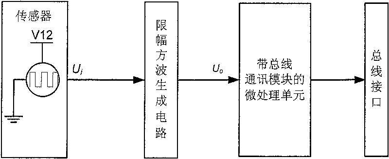
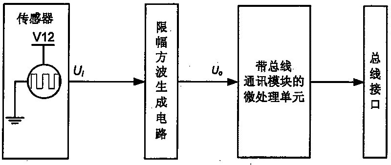
[0012] The vehicle speed sensor with bus interface that the present invention proposes is used for automobile, and its circuit block diagram is as follows figure 1 shown, including:

[0013] The sensor is used to convert the measured vehicle speed signal into a square wave voltage signal U i , and output to the limiting square wave generating circuit. The sensor is a Hall-type vehicle speed sensor. One end of the sensor is connected to a 12V power supply, the other end is connected to a ground signal, and the third end is connected to a limiting square wave generating circuit. When working, the sensor outputs an 8-12V square wave signal with variable frequency. .

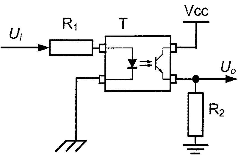
[0014] The limiting square wave generating circuit is used to receive the square wave voltage signal U output by the sensor i , and on the received square wave voltage signal U i Converted into a square wave voltage signal U with an amplitude of 0-5V o . The square wave voltage signal U o Output to the micro-...


PUM


Abstract

The invention relates to a speed sensor with a bus interface for an automobile, and belongs to the automobile electronic control technology field. The speed sensor comprises the sensor for convertingthe measured speed signal to the square wave voltage signal Ui; an amplitude limiting square wave generating circuit for receiving the output voltage signal of the sensor, converting into the square wave signal and carrying out the output; and a micro-processing unit with a bus communication module, wherein the micro-processing unit is used for carrying out the unit time counting of the received square wave signal Uo, converting the counting result to the value of the corresponding measured speed signal, carrying out the information frame coding of the value of the measured speed signal according to the transfer protocol, carrying out the conversion of the level signal of the information frame code according to the automobile bus protocol and sending the converted signal to the bus interface. The speed sensor can simplify the control of an automobile electric system, optimize the wire harness, save the space, carry out the real-time detection of the speed, convert the result to the digital signal and send to a communication bus through a bus interface.

Description

technical field [0001] The invention relates to a vehicle speed sensor with a bus interface for automobiles, belonging to the technical field of automobile electronic control. Background technique [0002] In the traditional automobile body electrical system, the sensor output signal of the car is directly connected to the signal receiver. When the same sensor signal is to be sent to multiple receivers, it is necessary to lead out multiple wires to connect to these receivers respectively. This connection method The wire connection in the vehicle is complicated, the space occupied is large, and the cost of the wiring harness is high. [0003] In the electrical system of modern automobile body, bus technology is applied more and more. For vehicles using bus technology, the output signal of the sensor is no longer directly connected to the receiver, but the sensor signal is converted into a digital signal by the controller and sent to the communication bus, and the receiver mo...

Claims


Application Information

Patent Timeline
Patent Type & Authority Patents(China)
IPC IPC(8): G01P3/44H04L12/40
Inventor 连小珉杨殿阁张新丰陆良薛雯罗禹贡李克强郑四发王建强
Owner TSINGHUA UNIV
Why Eureka
Try Eureka