Exterior member and wire harness

a technology of external members and wire harnesses, which is applied in the direction of electrical/fluid circuits, vehicle components, transportation and packaging, etc., can solve the problems of affecting the service life of the external member. , to achieve the effect of preventing shaving or the like on the conductive path side, avoiding the impact of conductive paths, and eliminating adverse influences on conductive paths

Active Publication Date: 2017-06-15
YAZAKI CORP
View PDF5 Cites 0 Cited by
  • Summary
  • Abstract
  • Description
  • Claims
  • Application Information

AI Technical Summary

Benefits of technology

[0013]According to the first aspect of the present invention, the plurality of protruding portions are disposed at positions which are on the helix around the tube axis and which are required to suppress movement of the conductive paths, the conductive paths can be prevented from moving easily, or the conductive paths can be held not to move.
[0014]According to the first aspect of the present invention, there is an advantage that the movement of the conductive paths within the exterior member can be suppressed in a desired position so that shaving or the like on the conductive path side can be prevented. In addition, according to the first aspect of the present invention, the exterior member is formed into a shape with no slit. Thus, there is an advantage that waterproofness, dust resistance, etc. can be secured, so that adverse influence on the conductive paths can be eliminated. Further, according to the first aspect of the present invention, as described above, the plurality of protruding portions are disposed at the positions on the helix around the tube axis. Therefore, as compared with a structure, for example, in which the plurality of protruding portions are arrayed with predetermined intervals along a straight line, it is possible to prevent the exterior member from being easily bent or broken even when the exterior member is subjected to an external force applied from a direction perpendicular to the array. As a result, there is an advantage that reduction of stiffness can be prevented. In other words, there is an advantage that necessary and sufficient stiffness can be ensured. Further, each of the plurality of protruding portions is substantially U-shaped or V-shaped and has a smooth surface, whereby there is an advantage that the one or more conductive paths can be smoothly inserted.
[0015]According to the second aspect of the present invention, the plurality of protruding portions are formed in the straight tube portion. Therefore, there is an advantage that the movement of the conductive paths within the exterior member can be suppressed in a desired position in the straight tube portion. As a result, there is an advantage that the movement of the conductive paths within a long range such as a vehicle underfloor (within a range where vibration of the conductive paths easily occurs) can be suppressed so that shaving or the like on the conductive path side can be prevented.
[0016]According to the third aspect of the present invention, since the wire harness includes the exterior member according to the first or second aspect, the wire harness can also obtain advantages described above. Therefore, there is an advantage that it is possible to provide a more excellent wire harness.

Problems solved by technology

When vibration during running of a vehicle is transmitted to the conductive path in such a reception state, there is a fear that the conductive path may vibrate and hit on the inner surface of the exterior member.
That is, there is a fear that shaving or the like may occur on the conductive path side.
However, there are the following technical problems in the wire harness described in JP-A-2014-212615.
One of the technical problems is that the wrap of tape is broken, for example, by the fly rock during driving of the vehicle, and water enters into the corrugated tube, for example, by splashed water, whereby failure is finally caused.
Further, there is another technical problem that since the exterior member having the slit portion is used, necessary and sufficient stiffness can not be ensured.

Method used


Image

  • Exterior member and wire harness
  • Exterior member and wire harness
  • Exterior member and wire harness

Examples


Embodiment Construction

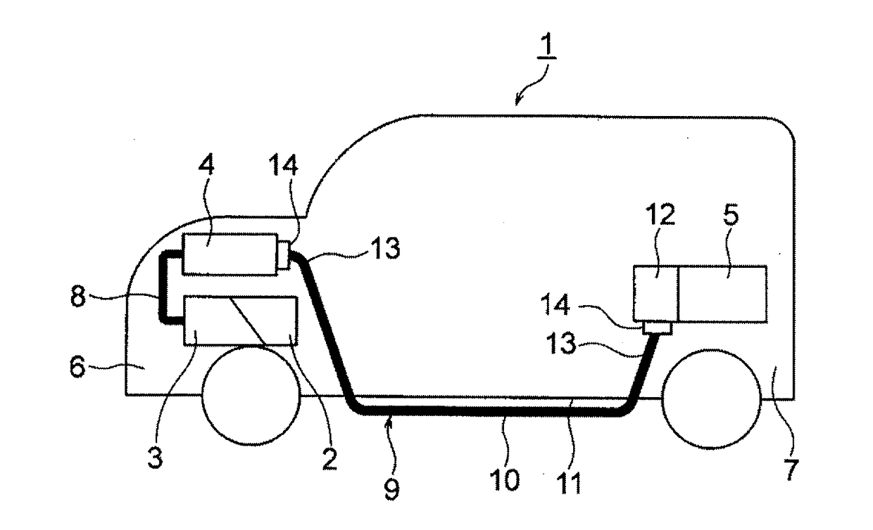
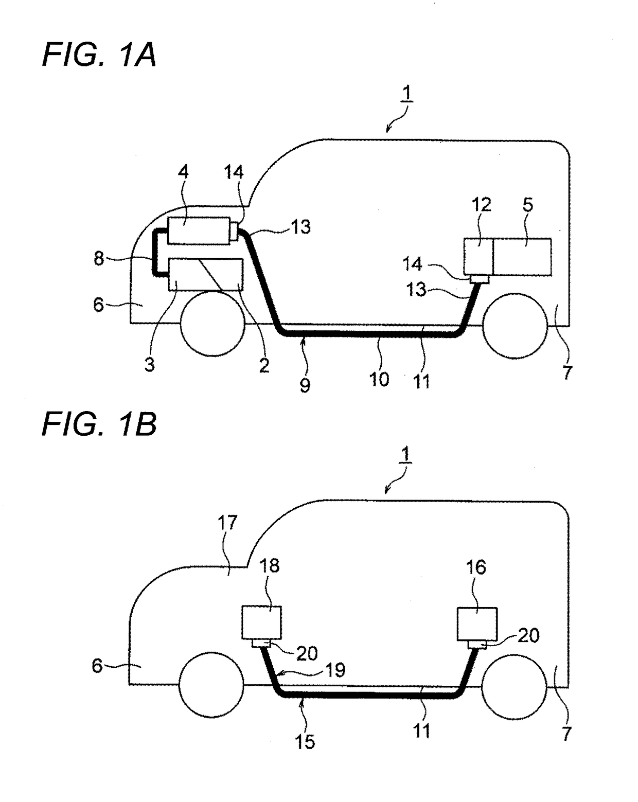
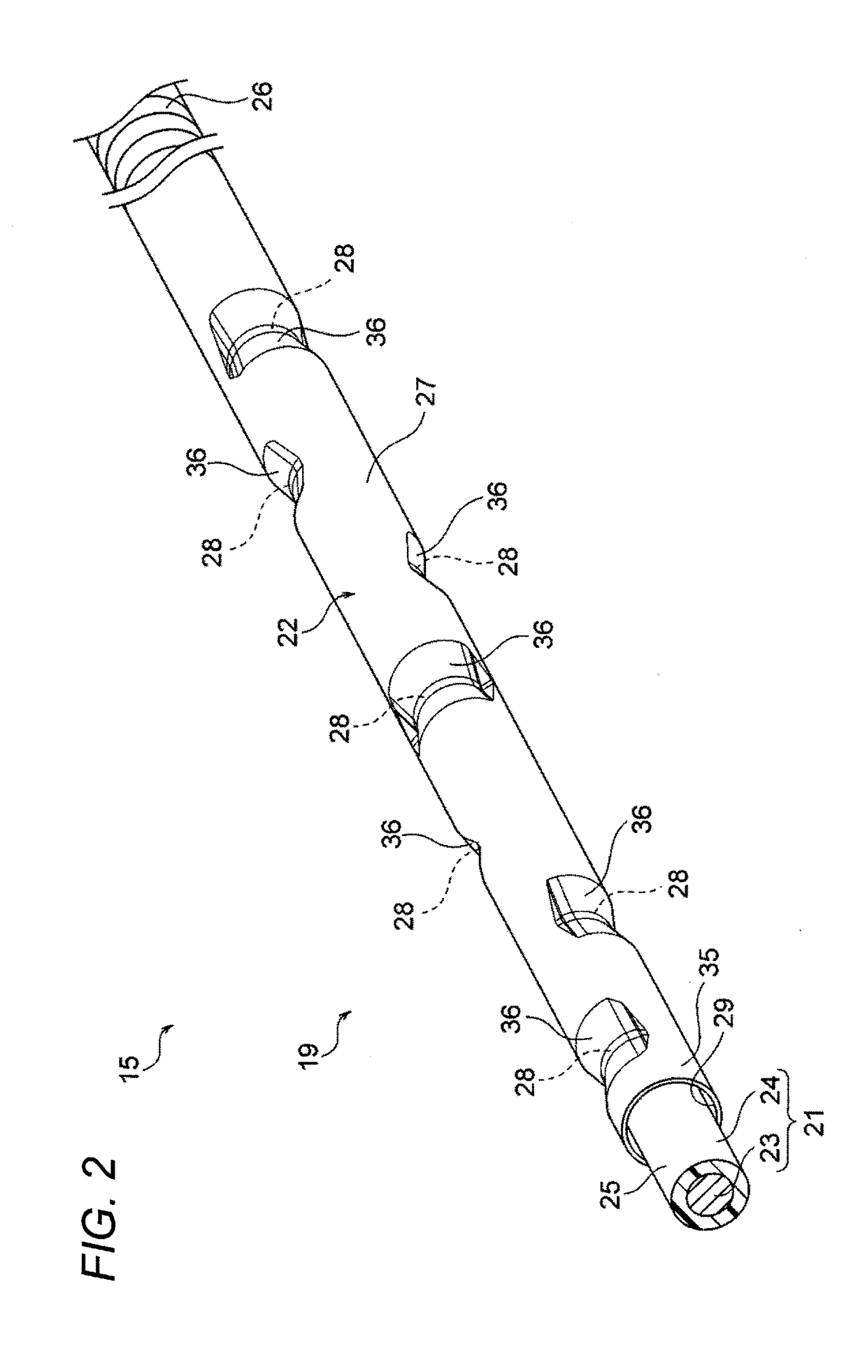
[0028]A wire harness includes an exterior member including a tubular body, and a conductive path stored and protected in the tubular body. The tubular body has no slit. The tubular body includes a plurality of protruding portions formed in, for example, a middle portion of, an inner surface of the tubular body. Each of the plurality of protruding portions is formed in a portion extending along a circumferential direction of an inner surface of the tubular body to have a substantially circular arc shape. Specifically, an R part is formed as the portion extending along the circumferential direction of the inner surface of the tubular body to have the substantially circular arc shape. Each of the plurality of protruding portions is substantially U-shaped or V-shaped in a cross-section cut along a tube axis of the tubular body and has a smooth surface. The plurality of protruding portions are disposed at positions on a helix around the tube axis.

[0029]An embodiment of the present invent...


PUM


Abstract

An exterior member includes a tubular body which allows one or more conductive paths to be stored and protected therein. The tubular body has no slit. The tubular body includes a plurality of protruding portions formed in an inner surface of the tubular body. Each of the plurality of protruding portions includes an R part having a substantially circular arc shape extending along a circumferential direction of an inner surface of the tubular body. Each of the plurality of protruding portions has a substantially U-shaped or V-shaped smooth surface in a cross-section cut along a tube axis of the tubular body. The plurality of protruding portions are disposed at positions on a helix around the tube axis.

Description

CROSS-REFERENCE TO RELATED APPLICATION(S)[0001]This application is based on and claims priority from Japanese Patent Application (Application No. 2015-242891) filed on Dec. 14, 2015, the entire contents of which are incorporated herein by reference.BACKGROUND[0002]1. Field of the Invention[0003]The present invention relates to an exterior member having a tube-like shape which allows a conductive path to be stored and protected therein, and a wire harness including the exterior member.[0004]2. Description of Related Art[0005]A high voltage wire harness will be described by way of example. For example, JP-A-2010-47032 discloses a wire harness for making electric connection between high voltage devices mounted on a hybrid car or an electric car. The wire harness disclosed in JP-A-2010-47032 by the present inventor includes one or plural conductive paths and a tube-like exterior member for protecting the one or plural conductive paths inserted thereto. The wire harness disclosed in JP-A...

Claims


Application Information

Patent Timeline
Patent Type & Authority Applications(United States)
IPC IPC(8): B60R16/02
CPCB60R16/0215
Inventor INAO, SHINICHIADACHI, HIDEOMI
Owner YAZAKI CORP
Why Eureka
Try Eureka