Automobile sensor with bus interface

A sensor system and bus interface technology, applied in the field of sensor systems, can solve the problems of high cost of wiring harness, complicated connection of wires in the car, large space occupation, etc., and achieve the effect of simple control, space saving, and optimization of wiring harness

Inactive Publication Date: 2010-01-27
TSINGHUA UNIV
View PDF6 Cites 0 Cited by
  • Summary
  • Abstract
  • Description
  • Claims
  • Application Information

AI Technical Summary

Problems solved by technology

[0002] In the traditional automobile body electrical system, the sensor output signal of the car is directly connected to the signal receiver. When the same sensor signal is to be sent to multiple receivers, it is necessary to lead out multiple wires to connect to these receivers respectively. This connection method Complicated connection of wires in the car, large space occupation and high cost of wiring harness

Method used


Image

  • Automobile sensor with bus interface
  • Automobile sensor with bus interface
  • Automobile sensor with bus interface

Examples


Embodiment Construction

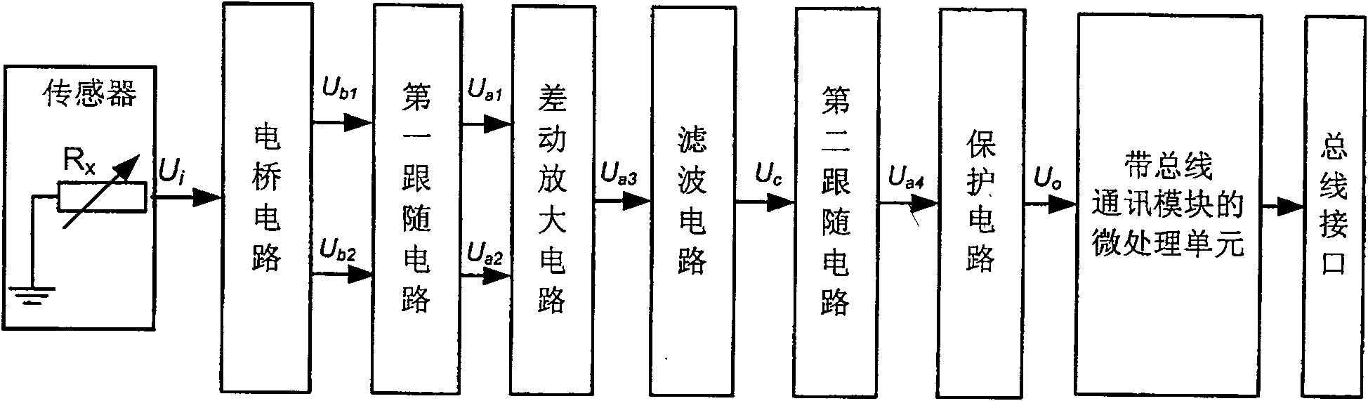
[0022] The sensor system with bus interface that the present invention proposes is used for automobile, and its circuit block diagram is as follows figure 1 shown, including:

[0023] The sensor is used to convert the measured physical signal into a resistance signal and convert the resistance signal U i Output to the bridge circuit, the sensor is a variable resistor R x One end of the variable resistor is connected to the ground signal, and the other end is connected to the bridge circuit. When working, its resistance value changes with the change of the measured signal.

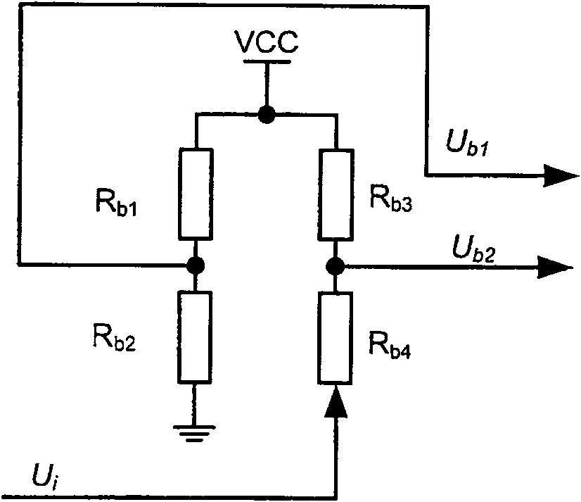
[0024] Bridge circuit for receiving the variable resistance sensor output signal U i , generating a differential signal U b1 and U b2 And output to the first follower circuit. The circuit principle of the bridge circuit is as follows figure 2 shown by the four resistors R b1 , R b2 , R b3 , R b4 Composition, connected in the form of a bridge. Resistance R b1 One end is connected to the digital ...


PUM


Abstract

The invention relates to a sensor with a bus interface for an automobile and belongs to the technical field of automobile electronic control, comprising a sensor that converts a measured signal to a resistance signal; a bridge circuit that generates a differential signal from the sensor signal; a first follower circuit that follows the differential signal; a differential amplifier circuit that differentially amplifies the signal; a filter circuit that filters the signal; a second follower circuit that follows the filter signal; a protection circuit that limits current and pressure of the signal; a microprocessor unit, which has a bus communication module and converts the modulus of a read signal, encodes the information frame of a physical signal according to a transport protocol, converts a level signal of the information frame code according to an automobile bus protocol, and at last sends the converted level signal to the bus interface. The sensor of the invention can detect the measured and output signal of the sensor in real time, convert the result to a digital signal and then send the signal to the communication bus by the bus interface.

Description

technical field [0001] The invention relates to a sensor system with a bus interface for automobiles, belonging to the technical field of automobile electronic control. Background technique [0002] In the traditional automobile body electrical system, the sensor output signal of the car is directly connected to the signal receiver. When the same sensor signal is to be sent to multiple receivers, it is necessary to lead out multiple wires to connect to these receivers respectively. This connection method The wire connection in the vehicle is complicated, the space occupied is large, and the cost of the wiring harness is high. [0003] In the electrical system of modern automobile body, bus technology is applied more and more. For vehicles using bus technology, the output signal of the sensor is no longer directly connected to the receiver, but the sensor signal is converted into a digital signal by the controller and sent to the communication bus, and the receiver monitors ...

Claims


Application Information

Patent Timeline
Patent Type & Authority Patents(China)
IPC IPC(8): B60R16/02G01D5/16
Inventor 连小珉杨殿阁陆良张新丰薛雯罗禹贡李克强郑四发王建强
Owner TSINGHUA UNIV
Why Eureka
Try Eureka