Full automatic silt separation apparatus

A fully automatic technology for sediment separation, applied in water conservancy projects, sea area projects, coastline protection, etc., can solve problems such as failure of hydroelectric generating units, and achieve the effects of saving water, reducing siltation, eliminating hazards and abrasion

Inactive Publication Date: 2011-06-15
黄国宏
View PDF4 Cites 0 Cited by
  • Summary
  • Abstract
  • Description
  • Claims
  • Application Information

AI Technical Summary

Problems solved by technology

The wear and tear of water turbines in hydropower production is particularly serious, making it impossible for the water turbine generator set to operate safely, stably, continuously and efficiently

Method used


Image

  • Full automatic silt separation apparatus
  • Full automatic silt separation apparatus
  • Full automatic silt separation apparatus

Examples


Embodiment Construction

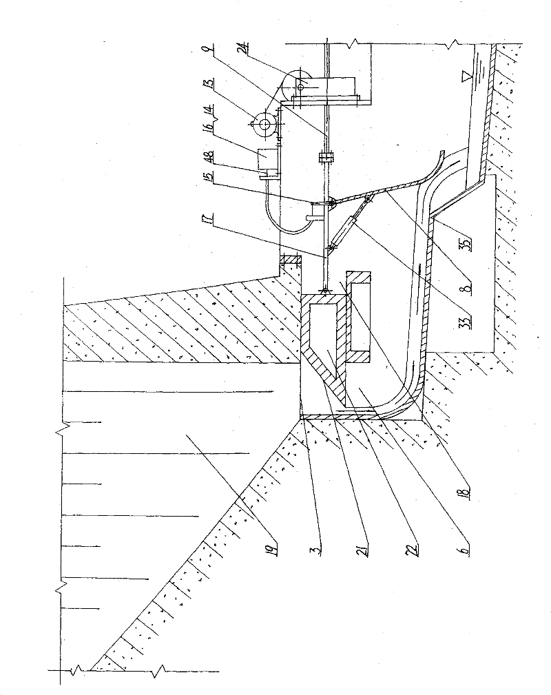
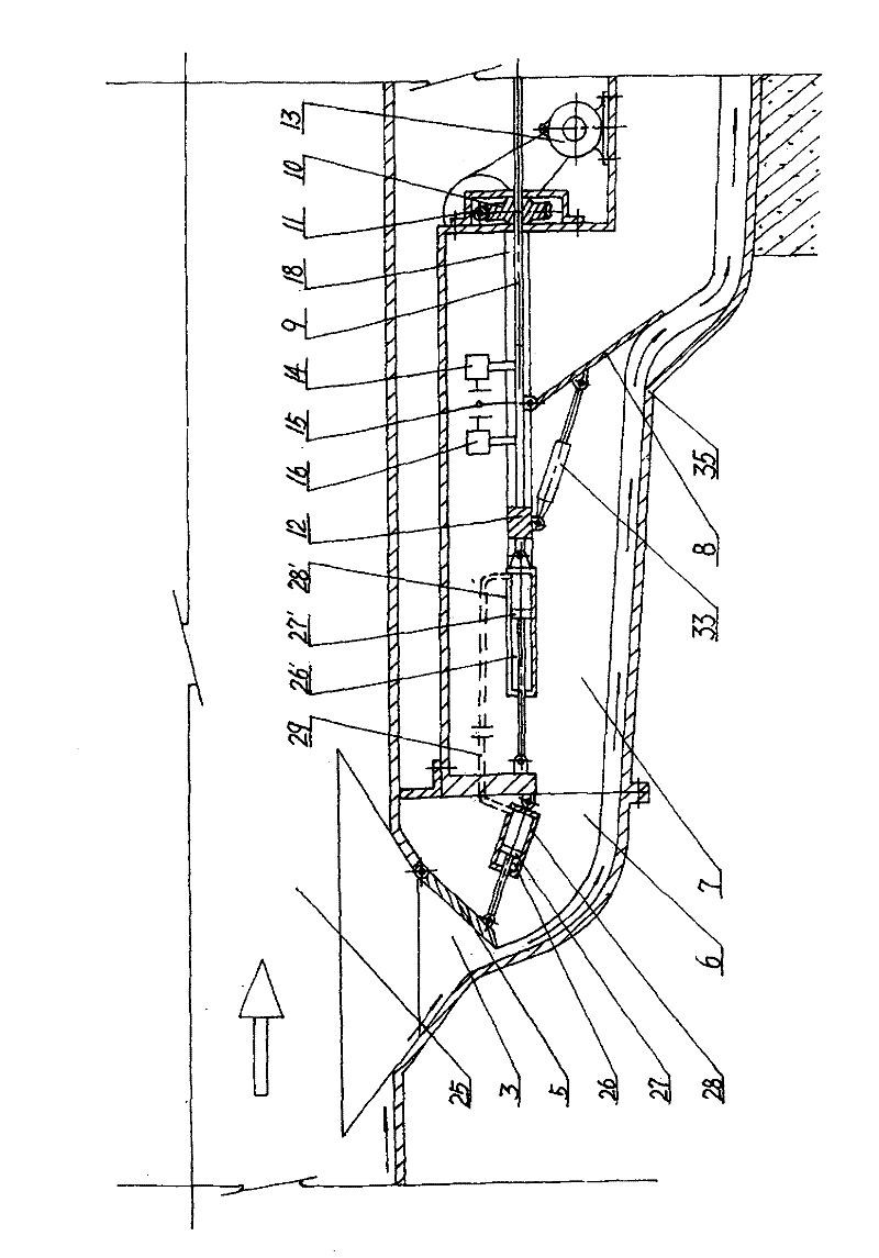
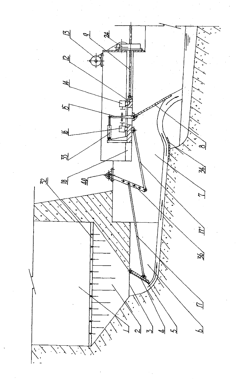
[0032] figure 1 A first embodiment of the invention is shown.

[0033] Such as figure 1 As shown: a trapezoidal groove 2 is developed at the bottom of the water diversion channel 1, and a rectangular sand discharge outlet 3 arranged horizontally is opened at the bottom of the trapezoidal groove 2, and a sand discharge flow channel 6 with a certain slope at the bottom is connected to the bottom of the rectangular sand discharge outlet 3 , the outlet end of the sand discharge channel 6 is connected to the falling water channel 7 provided with a pick-up ridge 34 . A trash rack 32 is arranged on the top surface level of the trapezoidal groove 2. A rectangular sand discharge throttling plate 5 is hinged on the edge of the rectangular sand discharge port 3 connected to the top surface of the sand discharge flow channel 6 , and seals 4 are arranged on both sides and the hinged end of the sand discharge throttle plate 5 . When the sand discharge throttling plate 5 hangs down, the d...


PUM


Abstract

The invention discloses a full-automatic silt separation device which relates to a full-automatic mechanical device which automatically separates silt brought by water current in a water passage or a silt sedimentation tank in time and automatically adjusts the desilting flow rate in time. The device is composed of a desilting throttle disc or a desilting throttle block which is arranged in the water passage, under a desilting port at the bottom of the silt sedimentation tank, or in a desilting passage, an automatic regulating device which is linked with the desilting throttle disc or the desilting throttle block by a transmission component or an electric circuit and arranged in the desilting passage connected with the desilting port, a power plant, an electric component, the electric circuit, and the like. The device not only can automatically separate the silt brought by water current by means of own structure in time, but also can automatically adjust the desilting flow rate in time according to the content of the silt, thereby being capable of completely separating the slit brought by water current under the condition of controlling the desilting flow rate to be in minimization.

Description

technical field [0001] The invention relates to a fully automatic mechanical device for automatically separating the sediment brought by the water flow in time and automatically adjusting the sand discharge flow in a water flow channel or a sediment sedimentation tank. Background technique [0002] At present, the separation of sediment in water conservancy projects mainly depends on the sand discharge hole or sand discharge outlet at the bottom of the water flow channel, dam or sedimentation tank, which is connected with the sand discharge hole or sand discharge orifice, and according to the horizontal The sand discharge gallery or sand discharge pipeline arranged in the direction, and the sand discharge gate or sand discharge gate valve installed on a certain cross section of the sand discharge gallery or sand discharge pipeline for sand discharge. Its shortcomings are: because there is a pressurized undercurrent in front of the sand discharge gate or the sand discharge ga...

Claims


Application Information

Patent Timeline
Patent Type & Authority Patents(China)
IPC IPC(8): E02B8/02
Inventor 黄国宏
Owner 黄国宏
Why Eureka
Try Eureka