
Full automatic pollution removing ice discharge apparatus

An ice removal device and fully automatic technology, which is applied in the cleaning of open water, water conservancy projects, artificial waterways, etc., can solve problems such as irremovable, destructive deformation, accidents, etc., and achieve the elimination of jamming, elimination of blocked flow channels, The effect of high safety and reliability

Inactive Publication Date: 2009-01-28
黄国宏
View PDF4 Cites 11 Cited by
  • Summary
  • Abstract
  • Description
  • Claims
  • Application Information

AI Technical Summary

Problems solved by technology

[0003] The above two kinds of cleaning machines and other cleaning machines currently used in water conservancy projects have the disadvantages that the sundries salvaged from the water surface cannot be cleaned automatically, which makes the cleaning rake unable to run continuously. When the clearance of the trash rack is reduced to the requirement for trash blocking, or when the water flow brings continuous debris, it will cause blockage of the flow channel; The debris falls into the upstream or downstream surface of the trash rack again, or the rake cannot slide down to the bottom due to the blockage of debris on the upstream surface of the trash rack
Its bigger deficiency is: the top structures of all the cleaning machines above will protrude from the water surface, so when the water flow brings ice, it cannot be removed.
The extensions fixed on the rotating grid bars not only cannot pass through the gap between the trash rack bars smoothly when debris is blocked, but also cannot bear the gravity of debris and the pressure of water flow
When the device is subjected to the gravity and pressure brought by debris and water flow, the extension of the trash rack and the rotating grid will also cause destructive deformation
Therefore, the above two kinds of cleaning machines cannot guarantee their safety and reliability, which will lead to serious accidents after being implemented in actual use.
Moreover, neither of the above two technologies has the function of cleaning dirt and deicing at the same time.
Therefore, it has not been promoted so far

Method used


Image

  • Full automatic pollution removing ice discharge apparatus
  • Full automatic pollution removing ice discharge apparatus
  • Full automatic pollution removing ice discharge apparatus

Examples


Embodiment Construction

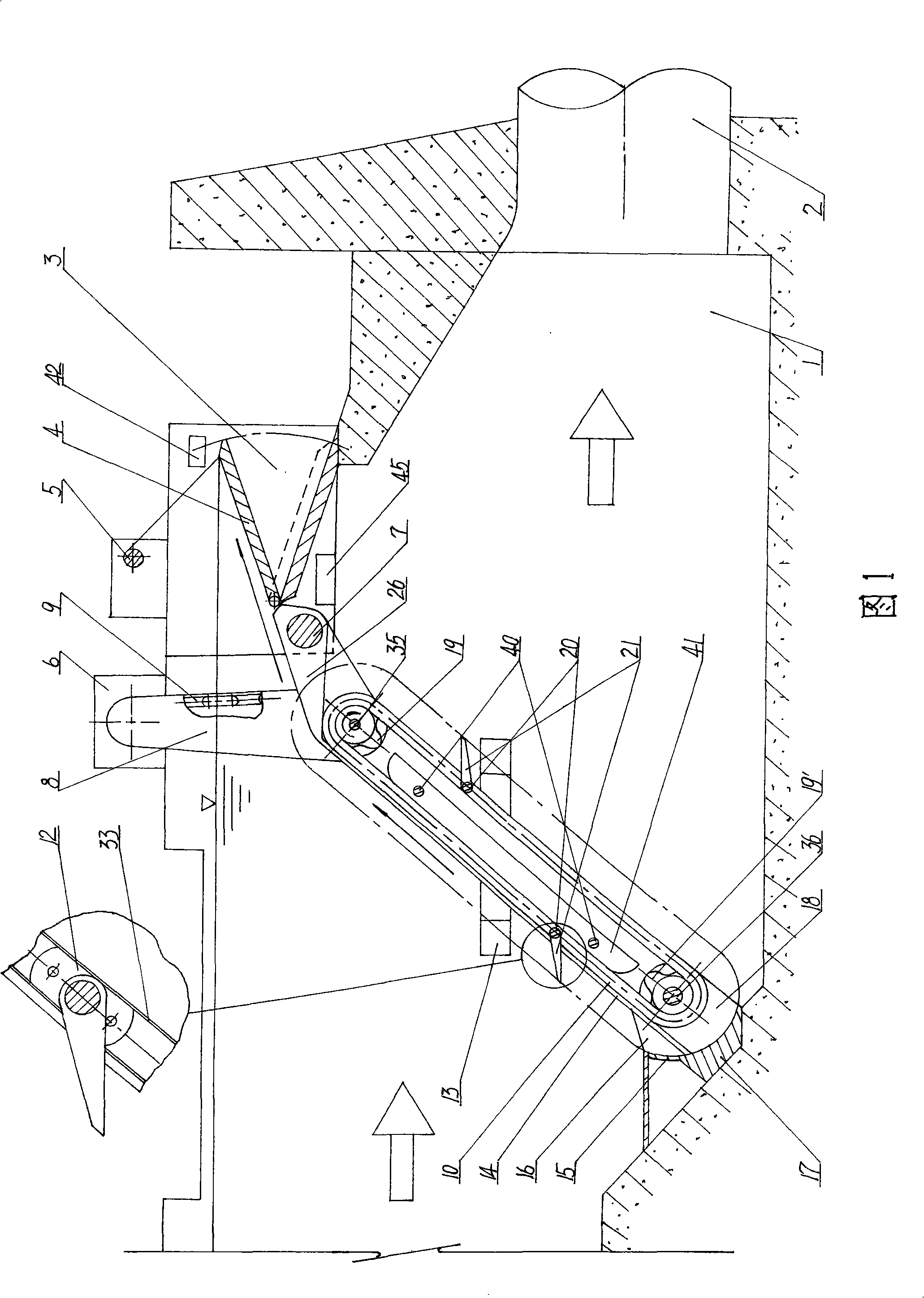
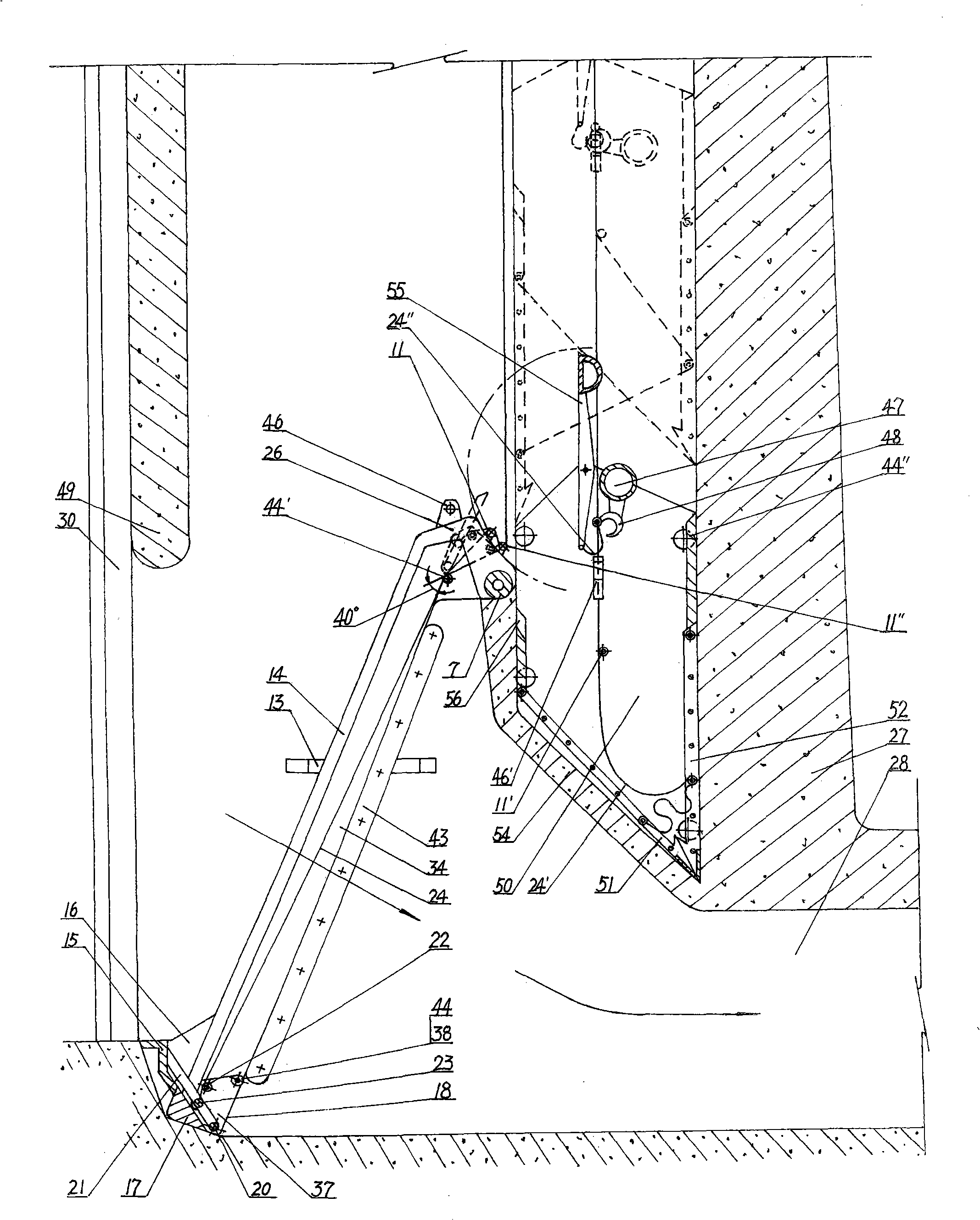
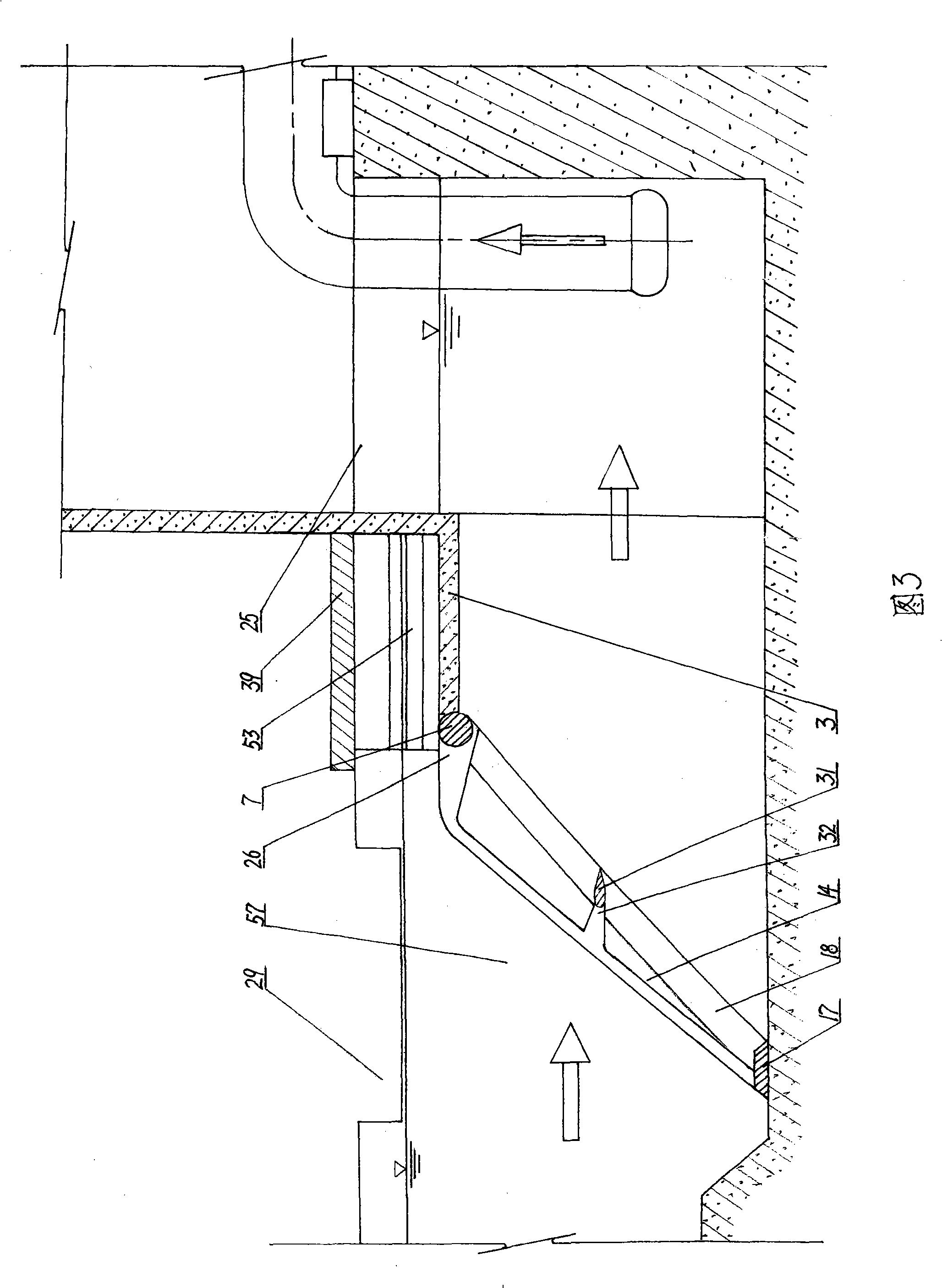
[0030] Figure 1 shows a first embodiment of the invention.

[0031] As shown in FIG. 1 : in the pressure forebay 1 , a sewage tank 3 is arranged on the top of the water inlet of the pressure pipe 2 . A grid frame composed of a top beam 7, a bottom beam 17 and two side beams 18 is installed on the cross-section between the bottom of the inlet end of the sewage tank 3 and the bottom of the pressure forebay 1. On the upstream surface of the top beam 7 of the grid frame, There are 100 cantilevers 26 that are arranged in parallel with each other and have a distance of 10 mm between each other. The other end of the cantilever 26 and the bottom beam 17 are respectively fixed with a cantilever composed of grid bars 14 after strong tension. Type folding trash rack. And the surface shape of the bottom beam 17 at the junction of the bottom beam 17 and the grid bar 14 is set as an arc-shaped mouth guard 15, and a tooth guard 16 is fixedly installed between the mouth guard 15 and the upst...


PUM


Abstract

The invention discloses a full-automatic sewage cleaning and ice removing device which relates to a full-automatic mechanical device that automatically and promptly clean and automatically discharge sundries and ice slush brought by water current in a water passage or a pressure fore bay of a diversion type hydropower station. The device comprises a dump tank at the top part of a flow passage or the pressure fore bay, and a sewage disposal door or a sewage sump thereof and a sewage funnel thereof, a cantilever type folded surface trash rack which is arranged on a water cross section between the dump tank or the sewage sump and the bottom part of the flow passage or the pressure fore bay, a mobile type sewage disposal rake arranged on the downstream face of the cantilever type folded surface trash rack, a pressure sensor, an electric circuit, a power plant, and the like. The device not only can automatically clean sundries and ice slush brought by water current by means of the own structure, but also can automatically discharge the sundries and the ice slush.

Description

technical field [0001] The invention relates to a full-automatic mechanical device for automatically cleaning and automatically discharging sundries and ice brought by water flow in a water passage or a pressure forebay of a diversion type hydropower station. Background technique [0002] At present, in the "chain rake cleaning machine" disclosed in Chinese patent 95206797.8 and the "trash rack cleaning machine" disclosed in 97217282.3, its composition and working process are: movable teeth are installed on the surface of the plane trash rack. The rake is driven by the power device through the chain or steel rope, and it makes reciprocating rotation or up and down movement on the surface of the plane trash rack. After the sundries blocked in the grid are salvaged from the water surface, they are turned over on the platform of the dam or picked up and then sent into the trolley. [0003] The above two kinds of cleaning machines and other cleaning machines currently used in w...

Claims


Application Information

Patent Timeline
IPC IPC(8): E02B5/08E02B15/10
Inventor 黄国宏
Owner 黄国宏
Learn More