Triplet commutation slurry valve

A slurry valve and three-way technology, which is applied in the field of reversing valves, can solve the problems of increasing investment and energy consumption, increasing installation space, and increasing the number of valves, and achieves compact structure, less space, and shorter opening and closing time. short effect

Inactive Publication Date: 2009-01-28
杭州耐特阀门股份有限公司
View PDF0 Cites 5 Cited by
  • Summary
  • Abstract
  • Description
  • Claims
  • Application Information

AI Technical Summary

Problems solved by technology

[0002] The existing alumina production process system needs to be equipped with a valve pipeline combination composed of multiple valves with a single opening and closing function to realize the different flow directions of the slurry or different media transmission; the disadvantage of this valve combination is: the process pipeline

Method used


Image

  • Triplet commutation slurry valve
  • Triplet commutation slurry valve
  • Triplet commutation slurry valve

Examples


Embodiment 1

[0034] This embodiment has the functions of pipeline merging, shortening and channel switching, which can merge and shorten two pipelines, and open and close them alternately according to process requirements.

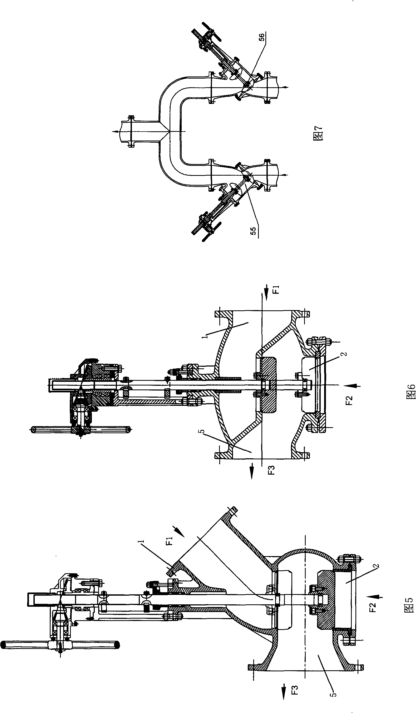
[0035] In the existing process pipeline, a slurry valve must be installed on each of the two pipelines to alternately open and close (as shown in Figure 7, a slurry valve 55 and a slurry valve 56 are respectively installed on the two pipelines).

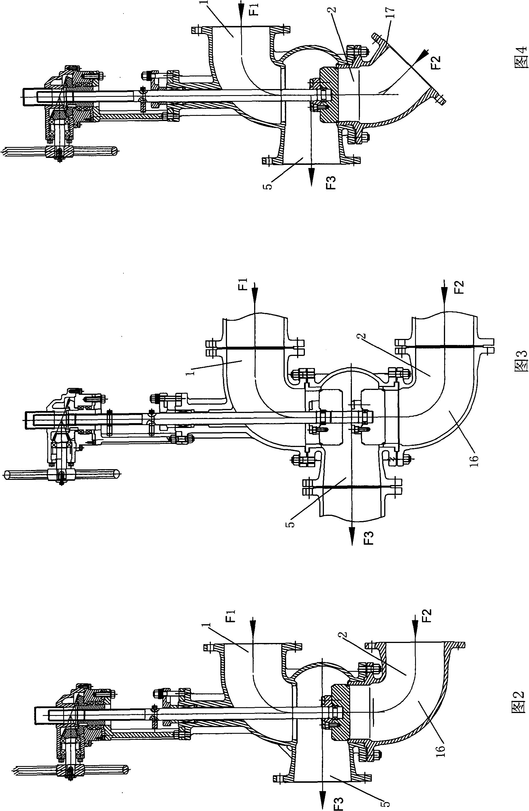
[0036] Adopting the utility model can replace the two pipelines and the two slurry valves to be alternately opened and closed (as shown in FIG. 2 ).

[0037] This embodiment also has multiple usage modes, by figure 1 to Figure 4.

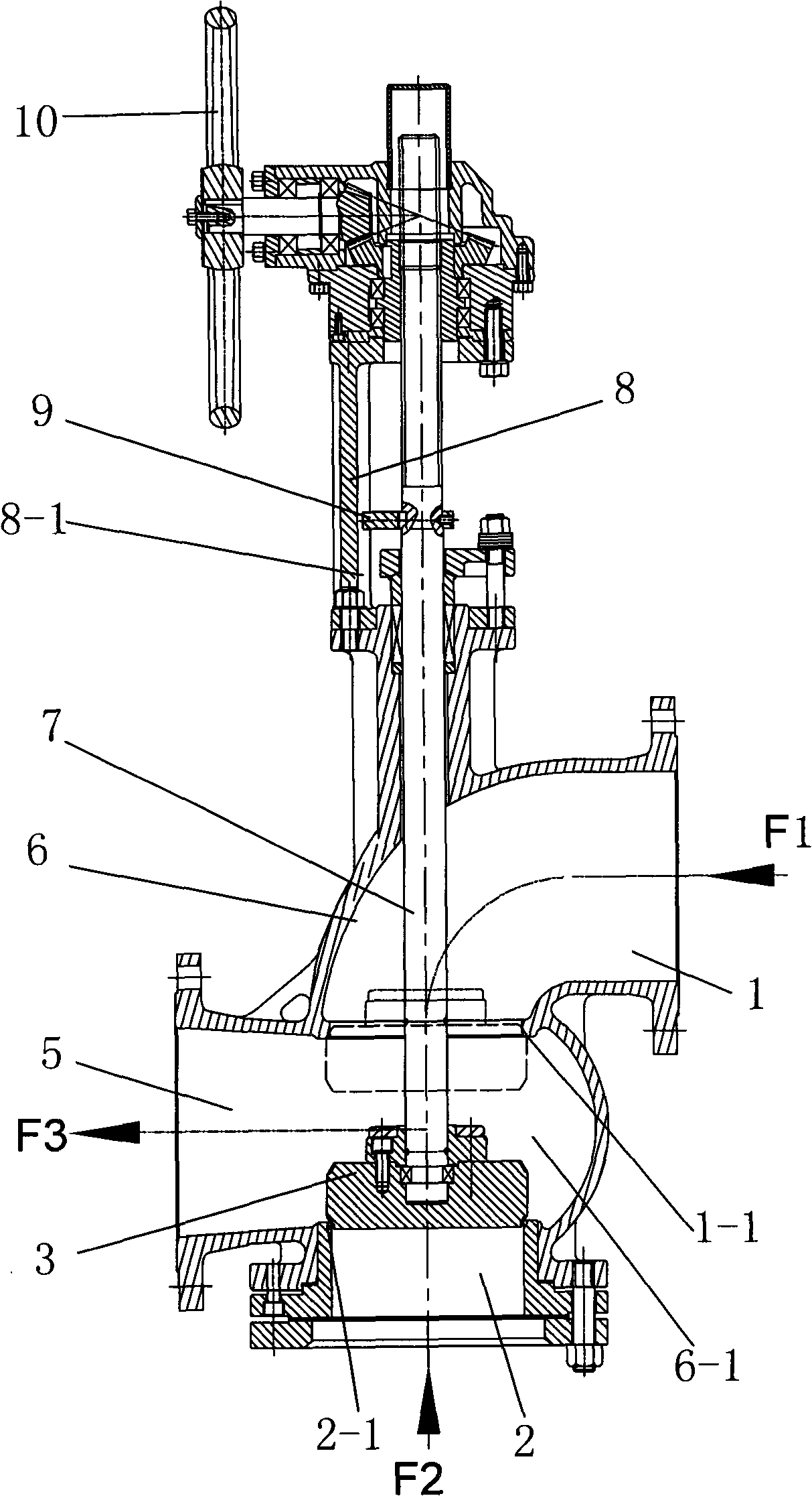
[0038] figure 1 Among them, the axes of the input ends of the two feed pipes (directly connected to the outlets of the two slurry delivery pumps) of the utility model are in a state of being perpendicular to each other.

[0039] Fig. 2 shows that the feed pipe 2 is provided with an extension val...

Embodiment 2

[0044] It is shown by the structure shown in Figure 5; its characteristic is that the axis of the input end of the discharge pipe 5 and the axis of the input end of the feed pipe 1 are arranged obliquely (135 degrees); its application method is determined by Figure 10 show. It has the function of simplifying the pipeline and reversing the opening and closing. It can change the direction of the two pipelines without disassembling the pipeline, and the reversing opening and closing is quick and convenient.

[0045] In the alumina process piping system, the design application has two decomposition tanks for alternate feeding; the conventional method is to share a reversing disassembly elbow ( Figure 9 shown) to connect the two decomposition tanks respectively. The operation of this method is relatively complicated; if the material is changed from the decomposition tank 21 to the decomposition tank 22, it is necessary to start the pneumatic discharge valve 28 on the tank wall t...

Embodiment 3

[0047] Shown by the structure shown in Figure 6, it is characterized in that the axis of the output end of the discharge pipe 5 coincides with the axis of the input end of the feed pipe 2; its application method is determined by Figure 12 show. It has the functions of easy operation, leakage prevention, and parallel reversing opening and closing. It can implement target decomposition tank discharge for multiple decomposition tanks using parallel pipelines according to process needs.

[0048] In the existing alumina process pipeline system, multiple slide valves are commonly used to implement alternate discharge of multiple decomposition tanks in parallel pipelines ( Figure 11 Shown; Such decomposition tanks can have many according to production needs, only draw two among the figure). The mode of operation is: close the gate valve 43 and the gate valve 42; open the gate valve 41 and the gate valve 45, and discharge the decomposition tank 21 (the slurry flows to S). Close th...


PUM


Abstract

The invention relates to a reversing valve, aiming at providing a valve which can realize the transportation of different flow directions and different media with simplified technological pipelines, reduced pipeline flow resistance and leakage; and the reversing valve is characterized in reduced investment outlay, reduced energy consumption and simplified and convenient technological operation. The technical proposal is that: the reversing valve comprises a valve body, a valve rod which penetrates the inner cavity of the valve body and can move linearly, a valve clack fixed at the top of the valve rod and a forcing mechanism which drives the movement of the valve rod; two mutually communicated feed pipes and a discharge pipe are arranged on the valve body; an upper valve base and a lower valve base are respectively formed at the connection places of the two feed pipes and the discharge pipe in the inner cavity of the valve body and have the same size and are opposite to each other; the central line of the two valve base coincides with the axis of the valve rod; the valve clack is positioned between the two valve bases; the upper and the lower end faces of the valve clack are respectively provided with seal faces that are respectively matched with the upper valve base and the lower valve base; when the valve rod drives the valve clack to move upward and downward, the seal faces respectively close a feed pipe and open another feed pipe.

Description

[0001] The invention relates to a reversing valve, in particular to a reversing valve used in a pressure pipeline system for conveying strong abrasive and corrosive materials. Background technique [0002] The existing alumina production process system needs to be equipped with a valve pipeline combination composed of multiple valves with a single opening and closing function to realize the different flow directions of the slurry or different media transmission; the disadvantage of this valve combination is: the process pipeline The extension or process pipeline (number) increases, the number of valves increases, the flow resistance of the pipeline increases, the leakage points increase, the installation space increases, the pipeline system is complicated, and the operation is complicated; the investment and energy consumption are correspondingly increased. Contents of the invention [0003] The technical problem to be solved by the present invention is to overcome the defici...

Claims


Application Information

Patent Timeline
IPC IPC(8): F16K11/044F16K31/44F16K27/00
Inventor 张孝方
Owner 杭州耐特阀门股份有限公司
Why Eureka
Try Eureka