I-shaped structure pressure and pull conversion force application apparatus

A technology of force applying device and pressure device, which is applied in the direction of measuring device, truss structure, measuring force, etc., can solve the problems of high cost of universal tensioning machine, unsafe hanging structure, long construction period, etc., and achieve safety in the construction process Fast, overall improvement and low construction cost

Inactive Publication Date: 2010-06-16
CHONGQING JIAOTONG UNIVERSITY
View PDF5 Cites 0 Cited by
  • Summary
  • Abstract
  • Description
  • Claims
  • Application Information

AI Technical Summary

Problems solved by technology

[0002] In the prior art, when testing the bearing capacity of the web of the I-shaped structure and the junction of the web and the upper and lower edge plates (especially when the web is welded to the upper and lower edge plates), the I-shaped structure Loading is usually done by setting ground anchors (or assembling giant reaction frames and other devices) on the prefabricated site, connecting with wire ropes, and performing I-shaped tension by tensioning jacks fixed on the ground anchors, which requires a large number of machinery and equipment and auxiliary facilities. There are many unsafe factors in the cantilever structure during the construction process, the process is complicated, the procedures are numerous, the technical difficulty is high, the cost of the measures is high, and the construction period is long; in order to solve the above problems, the theory of the universal tensioner appeared. If it can be realized, the construction speed will be significantly increase, but the cost of the universal tensioning machine is very high, so that the construction cost is greatly increased

Method used


Image

  • I-shaped structure pressure and pull conversion force application apparatus
  • I-shaped structure pressure and pull conversion force application apparatus
  • I-shaped structure pressure and pull conversion force application apparatus

Examples


Embodiment Construction

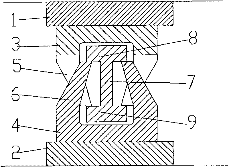
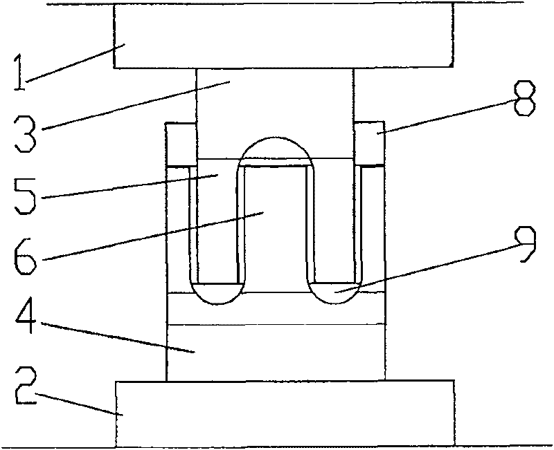
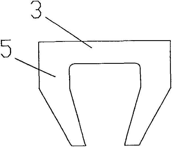
[0019] figure 1 It is a schematic cross-sectional view of the structure of the present invention, figure 2 It is a side view of the present invention, as shown in the figure: the I-shaped structure press-pull conversion force application device of the present invention includes a pressure device, an upper press block 3 and a lower press block 4, and the upper press block 3 and the lower press block 4 are both Longitudinal trough-like structure, the inner sides of the trough-like structure are bent toward the middle to form two top pressure sections, and the corners of the trough-like structure of the upper pressing block 3 and the lower pressing block 4 are arc transitions, eliminating the friction during the compression process. Stress concentration prolongs the service life of the device; when in use, the upper edge plate 8 and the lower edge plate 9 of the I-shaped structure are respectively located in the groove structure of the upper pressing block 3 and the lower pressi...


PUM


Abstract

The invention discloses a press and pull force converting device with an I-shaped structure, which comprises a pressure device, an upper press block and a lower press block, wherein, two jacking sections are formed by the step that the inner sides of the two sides of the grooved structures of the upper block and the lower block are bent towards the middle; the two jacking sections of the upper press block are respectively positioned at the two sides of an I-shaped web plate and are pressed downwards under a lower margin plate of the I-shaped structure, while the two jacking sections of the upper press block are respectively positioned at the two sides of the I-shaped web plate and are pressed downwards under an upper margin plate of the I-shaped structure; an upper load-bearing plate of the pressure device is arranged at the upper part of the upper press block, while a lower load-bearing plate thereof is arranged at the lower part of the lower press block; the device of the invention achieves pull resisting similar to the I-shaped structure by using a common pressure machine and arranges a ground anchor or assembles devices, such as a huge counter-force frame, and the like, in a preset filed, thereby greatly simplifies process, saving a large amount of rolled steel, avoiding the assembly of huge steel members, requiring no high measure costs for assembly, handling safety facilities, and the like, and improving working efficiency; during an anti-pull process, the integrity of the structure is increased remarkably and safety risk is greatly lowered, thus ensuring safety.

Description

technical field [0001] The invention relates to a force application device for a tensile structure, in particular to a pressure-tension conversion force application device for an I-shaped structure. Background technique [0002] In the prior art, when testing the bearing capacity of the web of the I-shaped structure and the junction of the web and the upper and lower edge plates (especially when the web is welded to the upper and lower edge plates), the I-shaped structure Loading is usually done by setting ground anchors (or assembling giant reaction frames and other devices) on the prefabricated site, connecting with wire ropes, and performing I-shaped tension by tensioning jacks fixed on the ground anchors, which requires a large number of machinery and equipment and auxiliary facilities. There are many unsafe factors in the cantilever structure during the construction process, the process is complicated, the procedures are numerous, the technical difficulty is high, the c...

Claims


Application Information

Patent Timeline
Patent Type & Authority Patents(China)
IPC IPC(8): G01L1/00E04C3/02
Inventor 龚尚龙孟云吴海军
Owner CHONGQING JIAOTONG UNIVERSITY
Why Eureka
Try Eureka