Shaft member for dynamic pressure bearing device

A technology for dynamic pressure bearings and shaft components, which is applied in the direction of bearing elements, sliding contact bearings, and rotating bearings, etc., and can solve the problem of depth or shape deviation of dynamic pressure grooves, inability to exert sufficient dynamic pressure, and decreased accuracy of outer peripheral surfaces, etc. problem, to achieve the effect of superior wear resistance

Inactive Publication Date: 2009-01-28
NTN CORP
View PDF4 Cites 4 Cited by
  • Summary
  • Abstract
  • Description
  • Claims
  • Application Information

AI Technical Summary

Problems solved by technology

[0010]However, usually, since the above-mentioned heat treatment is performed at a high temperature, deformation of the shaft itself is unavoidable, and there is a possibility that the accuracy of the outer peripheral surface may decrease
In particular, when the dynamic pressure groove is formed with a small size and high precision, the deformation of the shaft during heat treatment is likely to adversely affect the shape accuracy of

Method used


Image

  • Shaft member for dynamic pressure bearing device
  • Shaft member for dynamic pressure bearing device
  • Shaft member for dynamic pressure bearing device

Examples


no. 1 approach

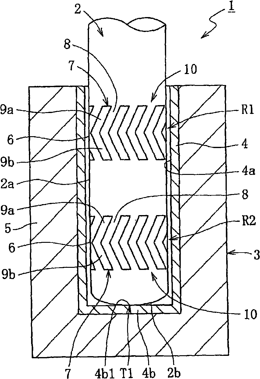
[0067] figure 1 A sectional view showing the dynamic pressure bearing device 1 of the first embodiment. In this figure, a dynamic pressure bearing device 1 includes a shaft member 2 and a bearing member 3 capable of inserting the shaft member 2 into the inner periphery.

[0068] In this embodiment, the bearing member 3 is a bottomed cylindrical body composed of an electroformed part 4 and a molded part 5, and the electroformed part 4 integrally or separately from the main body (master) is used as an insert part by integral injection molding of resin. The inner peripheral surface 4a of the electroformed portion 4 facing the outer peripheral surface 2a of the shaft member 2 has a perfect circular shape.

[0069] The shaft member 2 has a shaft shape with a constant diameter, and is made of, for example, a highly workable metal material (about 300Hv to 400Hv in terms of hardness) such as carbon steel, stainless steel, and various alloy steels. Of course, it is also possible to u...


PUM

PropertyMeasurementUnit
Hardnessaaaaaaaaaa

Abstract

Provided is a bearing member for a dynamic pressure bearing device, which is excellent in wear resistance and which can exhibit a high dynamic pressure action. A shaft material (11) is rolled to form a recess (7) for causing the dynamic action of a lubricant in a radial bearing clearance (6). Then, a surface layer portion (14) of the recess (7) to be formed on the outer circumference (11a) of the shaft material (11) is rolled to form a first hardened layer (14a). At the same time, a surface layer portion (15) of a surrounding area (8) of the recess (7) is also rolled to form a first hardened layer (15a) at its partial area. After the recess (7) was rolled, that shaft material (11) is barreled. As a result, the outermost surface layer of the surface layer portion (15) is barreled to form a second hardened layer (15b). The hardness of the second hardened layer (15b) formed in the surrounding area (8) is higher by 50 Hv to 200 Hv than that of the first hardened layer (14a) formed in the recess (7).

Description

technical field [0001] The present invention relates to a shaft member for a dynamic pressure bearing device. Background technique [0002] The dynamic pressure bearing device is a device that supports the shaft member in a relatively rotatable manner through the dynamic pressure of the fluid generated in the bearing gap. Recently, it is suitable for use as an information bearing due to its superior rotation accuracy, high-speed rotation, and quietness. Bearing devices for electric motors mounted on various electronic devices including machines. Specifically, it is used as a bearing device for spindle motors mounted on information equipment such as magnetic disk devices such as HDD, optical disk devices such as CD-ROM, CD-R / RW, and DVD-ROM / RAM, and optical disk devices such as MD and MO. , used as a multifunctional scanner motor for a laser beam printer (LBP), a color wheel motor for a projector, or a bearing device for motors such as fan motors. [0003] For example, in a...

Claims


Application Information

Patent Timeline
IPC IPC(8): F16C17/00F16C33/12
Inventor 日比建治山本康裕
Owner NTN CORP
Why Eureka
Try Eureka