Network fault detection method, apparatus and system

A technology of network failure and detection method, applied in the field of communication, can solve the problems of high cost, time-consuming and manpower, etc.

Inactive Publication Date: 2009-02-04
HUAWEI TECH CO LTD
View PDF0 Cites 4 Cited by
  • Summary
  • Abstract
  • Description
  • Claims
  • Application Information

AI Technical Summary

Problems solved by technology

[0005] The technical problem to be solved by the embodiments of the present invention is to provide a network fault detection method, device and system, to overcome the existing manual testing of the CLOS network by

Method used


Image

  • Network fault detection method, apparatus and system
  • Network fault detection method, apparatus and system
  • Network fault detection method, apparatus and system

Examples


Embodiment Construction

[0019] Embodiments of the present invention provide a network fault detection method, device, and system, which can overcome the existing manual testing of the CLOS network by using related testing instruments, which not only requires the use of special testing equipment, but also requires manual switching of testing interfaces. It takes a lot of time and manpower, and the cost is very high. In order to make the object, technical solution and advantages of the present invention clearer, the present invention will be further described in detail below with reference to the accompanying drawings and examples.

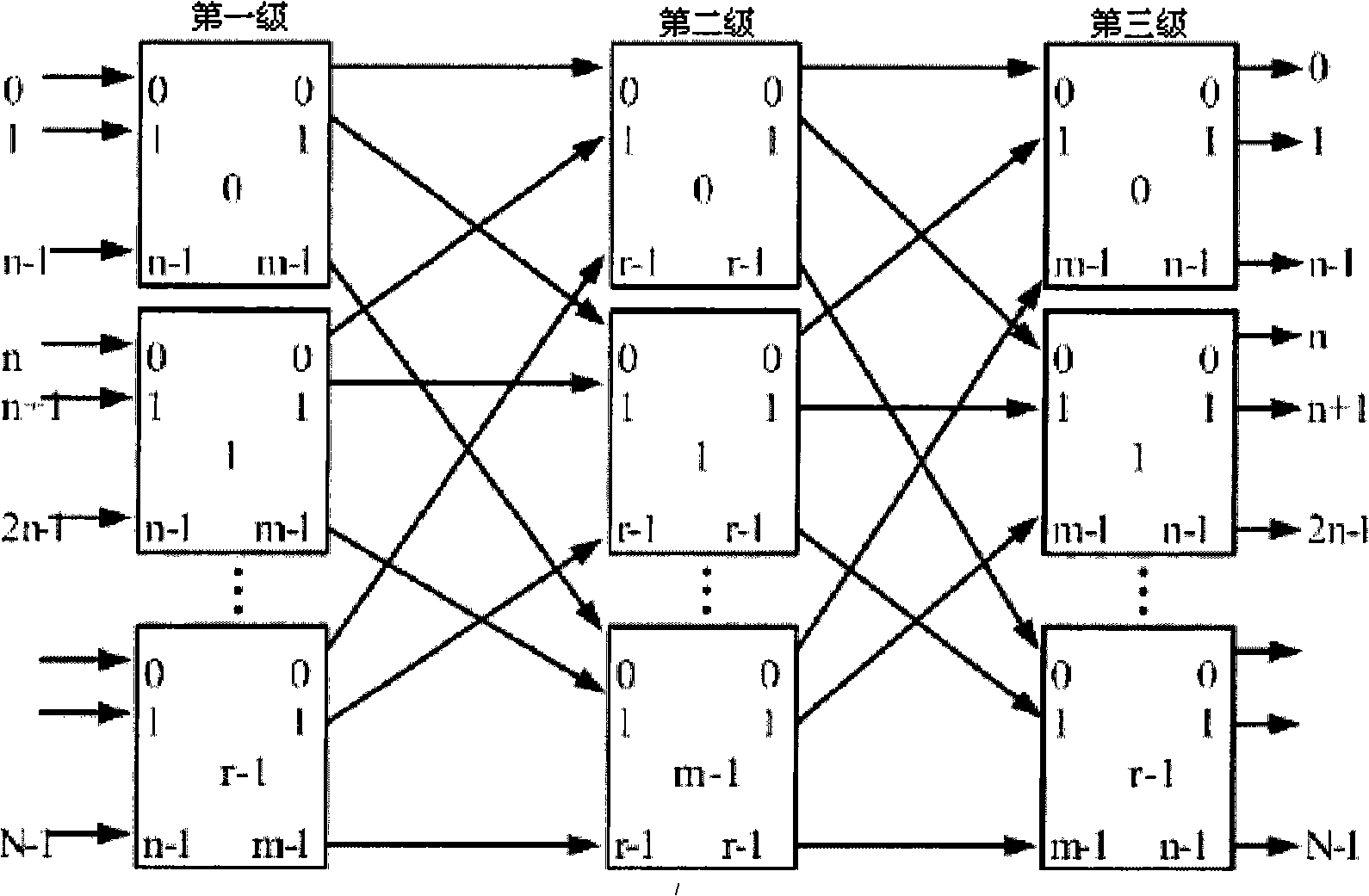
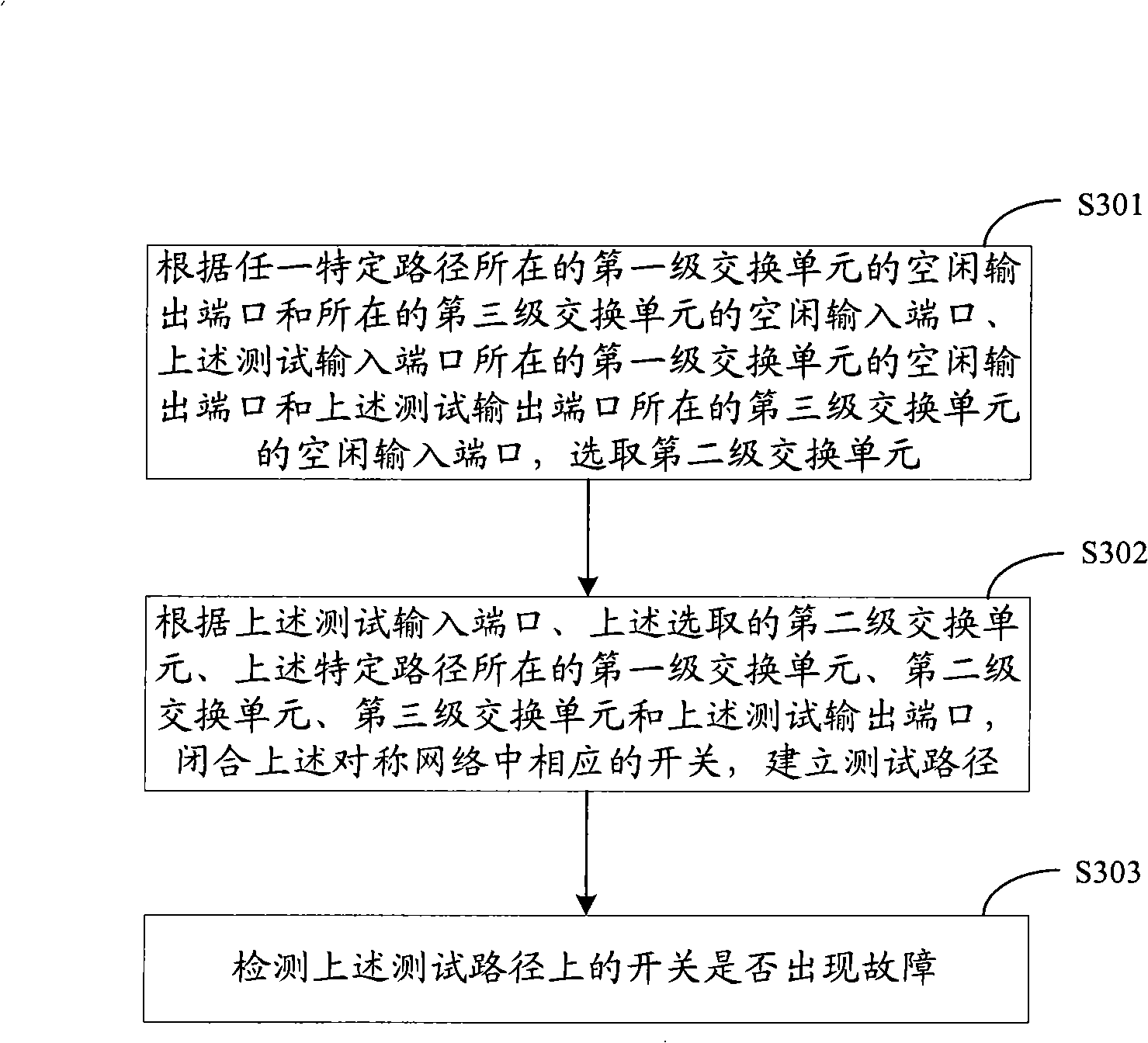
[0020] Such as image 3 As shown, it is a flow chart of a network fault detection method provided by an embodiment of the present invention, which is used for fault detection of an at least three-level symmetric network. The above-mentioned at least three-level symmetric network includes a first-level switching unit, a second-level Switching unit and third-level switching...


PUM


Abstract

An embodiment of the invention discloses a detection method of network failure, comprising: selecting a Level II exchange unit according to an idle output port of a Level I exchange unit that is the site of any specific path and an idle input port of a Level III exchange unit that is the site of any specific path, the idle output port of the Level I exchange unit that is the site of a test input port and the idle input port of the Level III exchange unit that is the site of a test output port; closing the corresponding switches in symmetrical network and building a test path according to the test input port, the selected Level II exchange unit, the Level I exchange unit that is the site of the specific path, the Level II exchange unit, the Level III exchange unit and the test output port; and detecting the switches on the test path to see whether fault exists. The invention also provides a device and a system for detecting network failure, realizing the fault detection to all switches in the whole CLOS network, and overcoming the defects of great time and labor input when switching test interfaces manually and costly undertaking.

Description

technical field [0001] The present invention relates to the communication field, in particular to a network fault detection method, device and system. Background technique [0002] The CLOS network was proposed by Charles Clos in 1953. A typical CLOS network is a three-level symmetrical network, such as figure 1 shown. Three levels: stage1, stage2, stage3, symmetrical: the number of incoming lines = the number of outgoing lines, the total number of incoming ports and the total number of outgoing ports are both N. figure 1 The direction is marked in , but in fact there is no direction, it only indicates the connection relationship. n indicates the number of input ports of Stage1 and the number of output ports of Stage3; m indicates the number of output ports of Stage1 and the number of input ports of Stage3; r indicates the number of input and output ports of Stage2. It can be seen that Stage1 has r n*m switching units, Stage2 has m r*r switching units, and Stage3 has r m*...

Claims


Application Information

Patent Timeline
IPC IPC(8): H04L12/26H04L12/24H04L1/24
Inventor 陈国导涂晓东
Owner HUAWEI TECH CO LTD
Why Eureka
Try Eureka