Performance optimization nylon zipper forming machine

A molding machine, nylon technology, applied in the direction of sliding fastener elements, applications, fasteners, etc., can solve the problems of increased resistance, low speed efficiency, monofilament wear, etc., to improve the damping effect, prolong the service life, and ensure stability. Effect

Inactive Publication Date: 2009-02-11
高碑店市高碑店视野拉链厂 +1
View PDF0 Cites 0 Cited by
  • Summary
  • Abstract
  • Description
  • Claims
  • Application Information

AI Technical Summary

Problems solved by technology

[0004] After long-term observation by the inventor, it is found that: 1. The forming device and the forming bracket have an unreasonable assembly method, which is inconvenient to operate and maintain, that is, the ejector rod mechanism and other forming device parts located under the top plate of the frame are not easy to install, disassemble, and observe. And maintenance
2. The front guard plate and screw anti-shake method of the vertical rod of the forming screw up and down position adjustment mechanism are unreliable. If the screw is tightened, the resistance will be large, and the anti-shake function will be lost if the screw is loose.
3. The lower end of the forming screw has a helical boss. When it rotates a circle, it can only wind the line once, and the speed efficiency is too low.
4. When the rotating sleeve-type monofilament lead mechanism pulls the monofilament for high-speed rotation, the rotating monofilament will strongly rub against the outer periphery of the bottom surface of the centerline bobbin holder, which will increase the resistance on the one hand and wear the monofilament on the other hand. A large amount of worn powder is produced, which pollutes the environment and equipment after flying
Furthermore, the inventor also found that it has the problems of unstable operation, high noise, strong vibration, large starting resistance, and large wear and tear.
It has the disadvantages of inconvenient operation and maintenance, poor performance and reliability

Method used


Image

  • Performance optimization nylon zipper forming machine
  • Performance optimization nylon zipper forming machine
  • Performance optimization nylon zipper forming machine

Examples


Embodiment Construction

[0021] Below in conjunction with the accompanying drawings and specific examples for further description

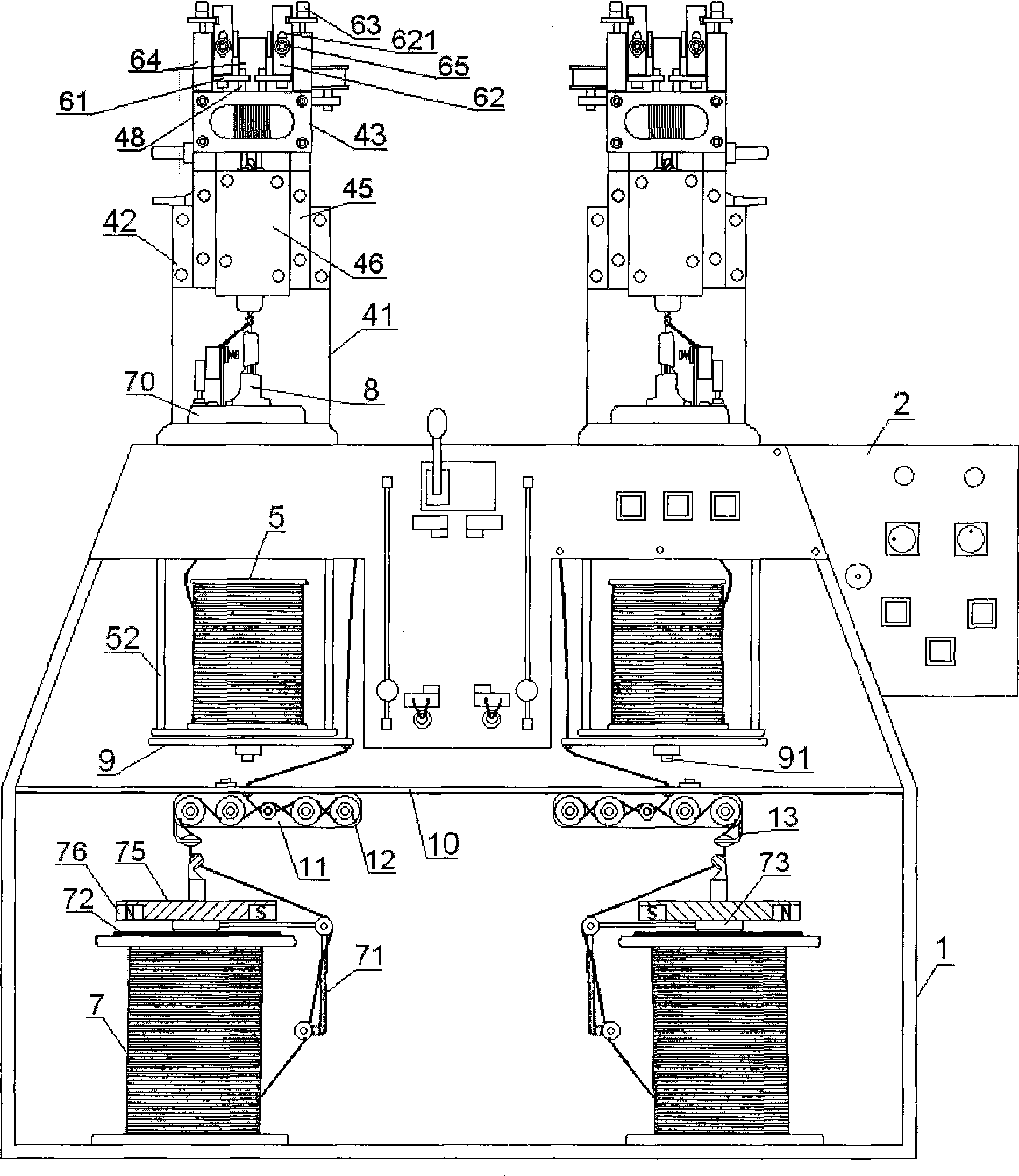
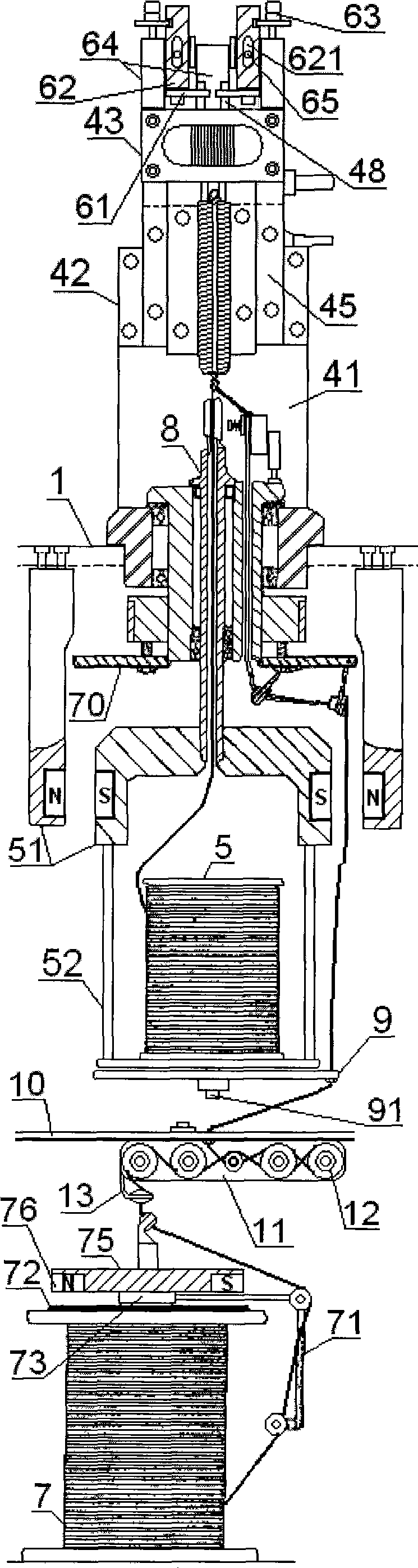
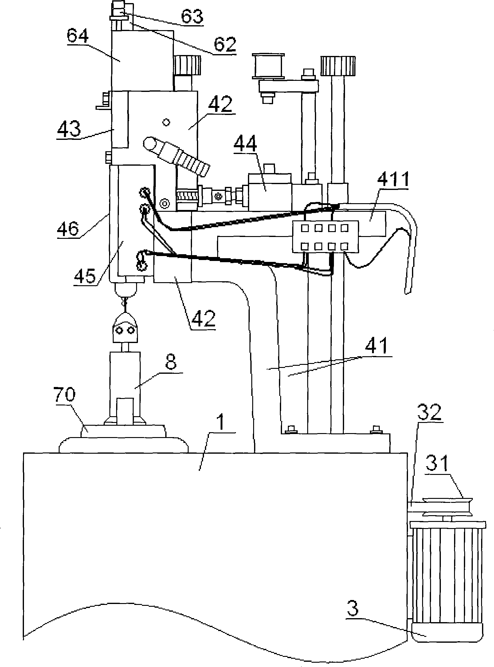
[0022] As shown in the figure, the performance-optimized nylon zipper forming machine of the present invention includes a frame 1 whose upper part is a small trapezoidal shape, an electric control box 2 mounted on one side of the upper part of the frame 1, a motor 3, and a motor 3 installed on the frame 1. The molding device above drives the two parallel main shafts of the molding device, and the feeding device installed in the frame 1 drives the two parallel auxiliary shafts of the feeding device. The molding device comprises a support frame 41 with a top plate 411 fixed on the top of the frame 1 arranged side by side, and an inverted T-shaped support plate 42 fixed on the front end of the frame top plate 411; the inverted T-shaped support plate 42 top surface is fixed with The upper and lower position adjustment mechanism of the forming screw, the forming screw drive me...


PUM


Abstract

The invention relates to a performance optimization type nylon zipper molding machine which aims at solving the problems that the existing molding machine has inconvenient operation and maintenance, as well as poor reliability; the molding machine comprises a rack, a molding device and a feed device; the molding device includes support frames with top plates on the upper surfaces, which are left and right parallelly distributed and fixed on the rack, as well as a T-typed support plate which is fixedly arranged at the front ends of the top plates of the rack; the top face of the T-typed support plate is fixedly provided with a molding screw upper and lower position adjustment mechanism; the upper part of the T-typed support plate is provided with a molding screw driving mechanism; the rear side of the middle part of the T-typed support plate is provided with a top rod mechanism; and the front face of the middle lower part of the T-typed support plate is provided with a heating plate and a mold plate; the T-typed support plate is an inverted T-typed support plate, and the rear face of the lower end with side ears at the two sides is fixedly connected with the front ends of the rack top plates; and a top rod mechanism is arranged on the rack top plates. The molding machine simplifies the structure, facilitates the installation, maintenance, adjustment, operation, maintenance and observation, can greatly improve the damping effect under the high-speed operation, is conducive to guaranteeing the single-wire supply speed, tension stability and product quality, is conducive to prolonging the service life, and has the advantages of strong reliability, stable operation, less noise, small vibration, small start-up resistance, less wear and good stability.

Description

technical field [0001] The invention relates to a zipper manufacturing equipment, in particular to a performance-optimized nylon zipper forming machine. Background technique [0002] The existing zipper forming machine closest to the present invention includes a frame, an electric control box, a motor, a forming device installed on the frame, two main shafts driving the forming device, and a feeder installed in the frame. device. Wherein, the molding device includes a support frame with a top plate fixed on the frame and fixed on the top of the frame, a T-shaped support plate fixed on the front end of the support frame top plate, the upper back of the upper part with side ears on both sides of the T-shaped support plate and the support frame top plate. The front end is fixedly connected, and the top surface of the T-shaped support plate is fixed with the upper and lower position adjustment mechanism of the forming screw; the upper part of the T-shaped support plate is equip...

Claims


Application Information

Patent Timeline
Patent Type & Authority Applications(China)
IPC IPC(8): A44B19/42
Inventor 郑根植
Owner 高碑店市高碑店视野拉链厂
Why Eureka
Try Eureka