Elevating mechanism of objective table

A lifting mechanism and stage technology, which is applied to workbenches, manufacturing tools, etc., can solve the problems of inability to adjust the processing requirements of the equipment flexibly, inaccurate transmission, etc., and achieve the effect of flexible stroke changes, accurate transmission, and high transmission efficiency.

Inactive Publication Date: 2009-02-11
庄添财
View PDF0 Cites 17 Cited by
  • Summary
  • Abstract
  • Description
  • Claims
  • Application Information

AI Technical Summary

Problems solved by technology

[0002] When manufacturing bicycles, two rows of holes are usually processed on the front and rear rims of the bicycle to install bicycle spokes; since the distance difference between the two rows of holes in the axial direction of the rim is very small, in the prior art, ordinary cylinders are used The transmission is imprecise; in addition, for the rims of different specifications, the distance between the two rows of holes is also different, and the original equipment cannot be flexibly adjusted according to the processing requirements

Method used


Image

  • Elevating mechanism of objective table
  • Elevating mechanism of objective table
  • Elevating mechanism of objective table

Examples


Embodiment Construction

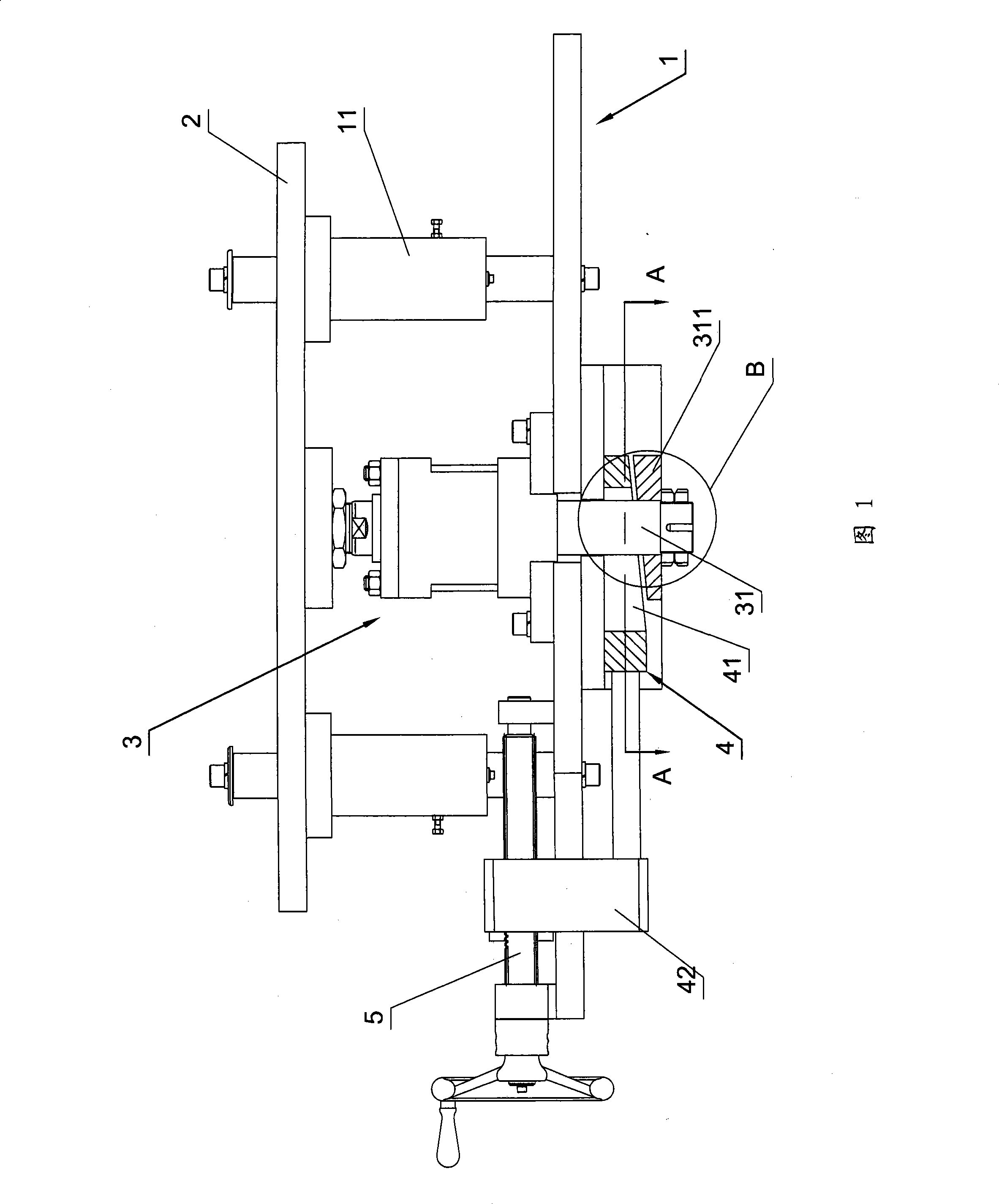
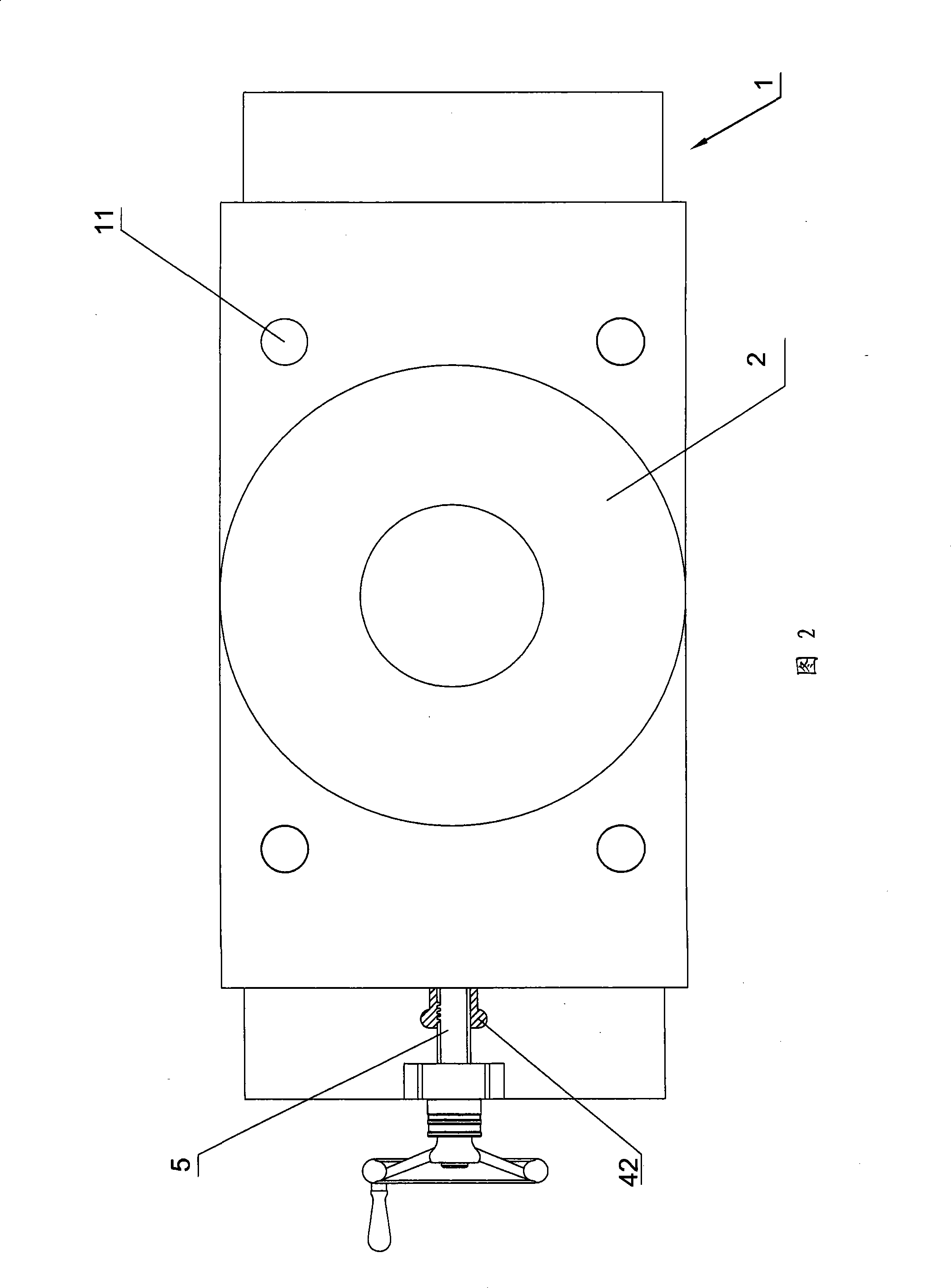
[0013] Referring to accompanying drawings 1 to 5, a lifting mechanism for a stage includes a seat body 1 connected to a supporting object, and a connecting plate 2 fixedly connected to the stage. Usually, the seat body 1 is a large A part of the frame of the equipment, and the connecting plate 2 can also be directly used as a stage for carrying workpieces.

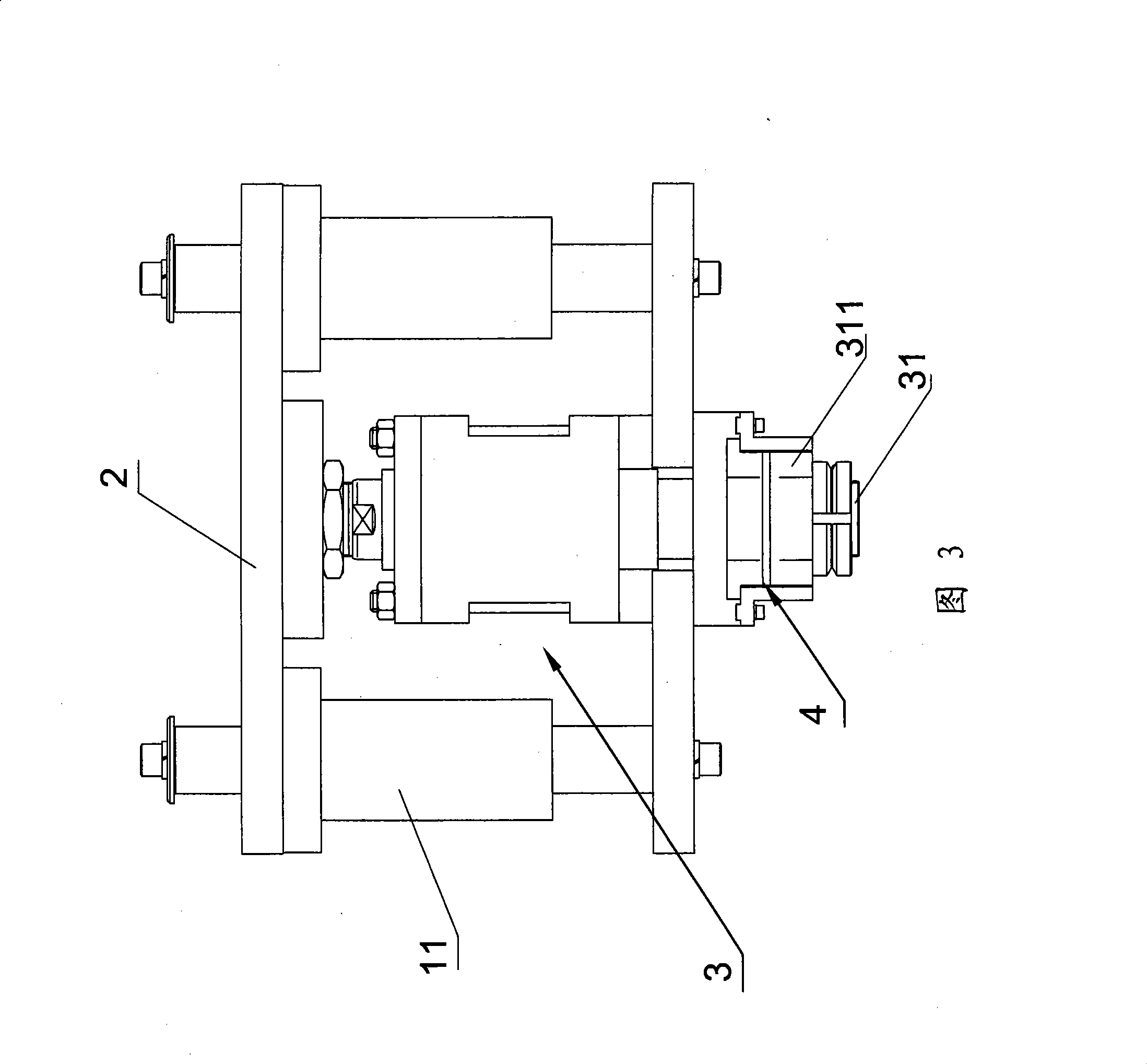
[0014] The seat body 1 has a plurality of guide rods 11 arranged in the vertical direction, the connecting plate 2 is slidably sleeved on the guide rods 11, and the connecting plate 2 can be vertically slid along the guide rods 11 to realize the lifting of the rim ( The "vertical direction" described in this specification refers to the up-down direction in accompanying drawing 1).

[0015] Cylinder 3 is also fixedly arranged on seat body 1, and cylinder 3 adopts double outlet rod cylinder, as shown in accompanying drawing 1, cylinder 3 has piston rod 31 that is arranged along the vertical direction, and the upper end and l...


PUM


Abstract

The invention relates to an elevating system of an objective table. The elevating system comprises a seat body and a connecting plate which can be arranged on the seat body by sliding, an air cylinder is fixedly arranged on the seat body, a piston rod arranged along the perpendicular direction is arranged on the air cylinder, the upper end and the lower end of the piston rod are respectively traveled through the air cylinder, the upper end of the piston rod is fixedly connected with the connection plate, the lower end of the piston is fixedly connected with a wedge-shaped lower inclined block, an upper inclined block which can be moved along the horizontal direction is also arranged on the seat body, a groove is arranged on the upper inclined block, the piston rod passes through the groove, the upper surface of the lower inclined block is parallel to the lower surface of the upper inclined block, the lower surface of the upper inclined block and the upper surface of the lower inclined block are respectively intersected with a plumb line, and the connecting line between the two intersection points is the stroke of the objective table; the flexible change of the stroke of the air cylinder is realized through a pair of wedge-shaped inclined blocks, and the accurate control for the stroke can be achieved through the drive of a screw rod. The elevating system has the advantages that the drive efficiency is high, the drive is accurate, the adjustment is convenient, and the stroke can be flexibly changed.

Description

technical field [0001] The invention relates to an elevating mechanism of a loading platform, which is especially suitable for use when the stroke of the loading platform is small and the stroke is flexible and changeable. Background technique [0002] When manufacturing bicycles, two rows of holes are usually processed on the front and rear rims of the bicycle to install bicycle spokes; since the distance difference between the two rows of holes in the axial direction of the rim is very small, in the prior art, ordinary cylinders are used The transmission is imprecise; in addition, for the rims of different specifications, the distance between the two rows of holes is also different, and the original equipment cannot be flexibly adjusted according to the processing requirements. Contents of the invention [0003] The object of the present invention is to provide a loading platform elevator with precise transmission and flexible stroke. [0004] drop mechanism. [0005] ...

Claims


Application Information

Patent Timeline
Patent Type & Authority Applications(China)
IPC IPC(8): B25H1/16
Inventor 刘家真王伟
Owner 庄添财
Why Eureka
Try Eureka