Cable protection and guide device

A guiding device and cable technology, applied in cable installation, cable arrangement between relatively moving parts, transportation and packaging, etc., can solve problems such as bending movement obstacles, complicated connection and assembly operations, and manufacturing errors of left and right link plates , to achieve the effect of halving the production cost, simplifying the supply management of parts, and reducing the production cost

Active Publication Date: 2014-12-10
TSUBAKIMOTO CHAIN CO
View PDF11 Cites 0 Cited by
  • Summary
  • Abstract
  • Description
  • Claims
  • Application Information

AI Technical Summary

Problems solved by technology

[0004] However, there is a problem in the cable protection and guiding device of the above-mentioned Patent Document 1, that is, since it is necessary to form a pair of left and right link plates using separate molds on the left and right, the manufacturing cost of the link plate mold cannot be reduced, and it can be used in the desired production. When the shape of the link plate has a variety of functions, there is a problem in mold production that often doubles the production cost of the link plate mold. In addition, there is a problem in the handling of the following parts: when connecting and assembling, it is necessary to align the left and right A pair of link plates is used to properly manage the supply of parts, and the left and right pair of link plates must be selected and identified for assembly, so the connection and assembly work is complicated, and the manufacturing error between the left and right link plates may also affect the bending after completion. movement brings obstacles

Method used


Image

  • Cable protection and guide device
  • Cable protection and guide device
  • Cable protection and guide device

Examples


Embodiment Construction

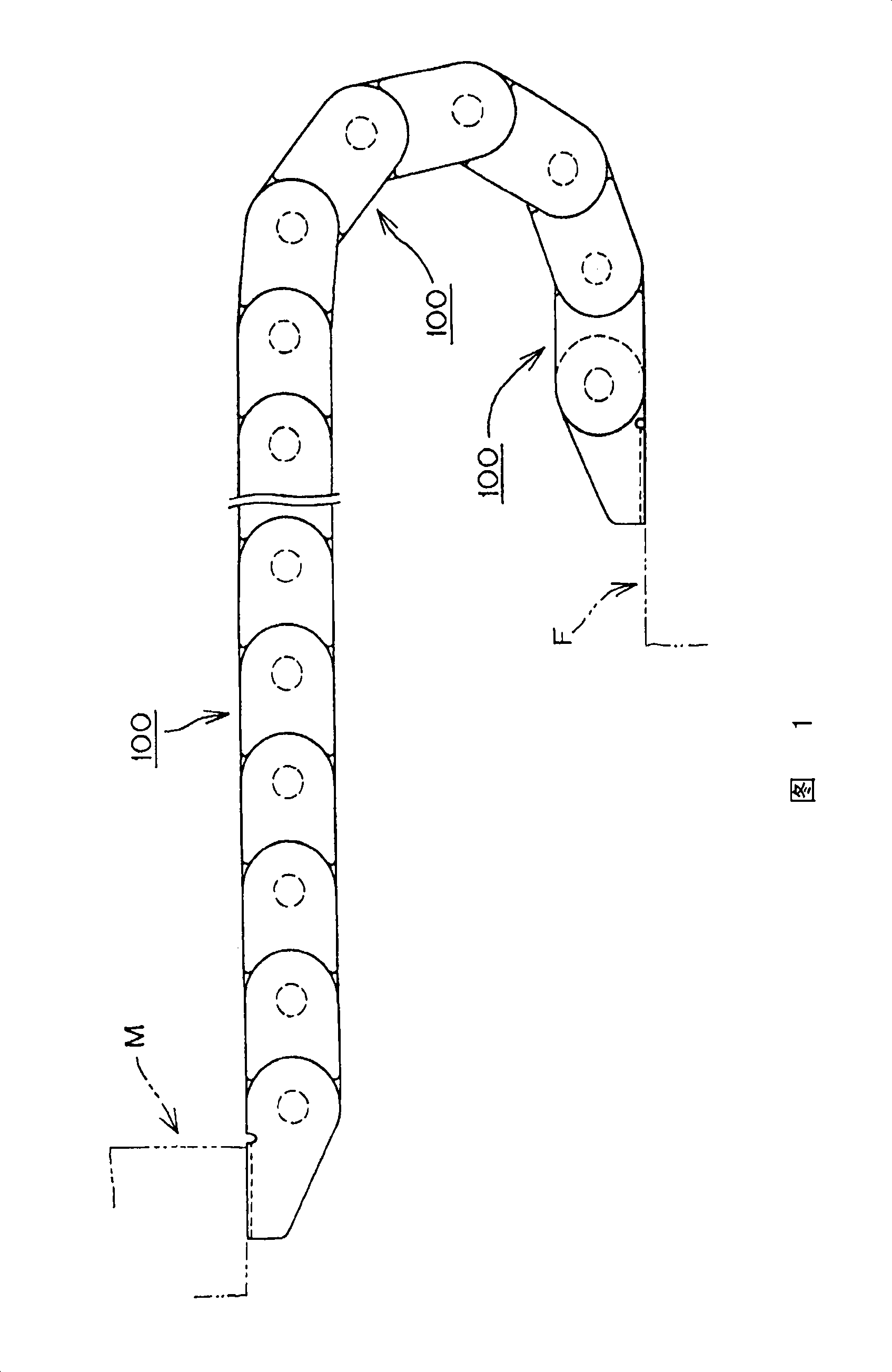
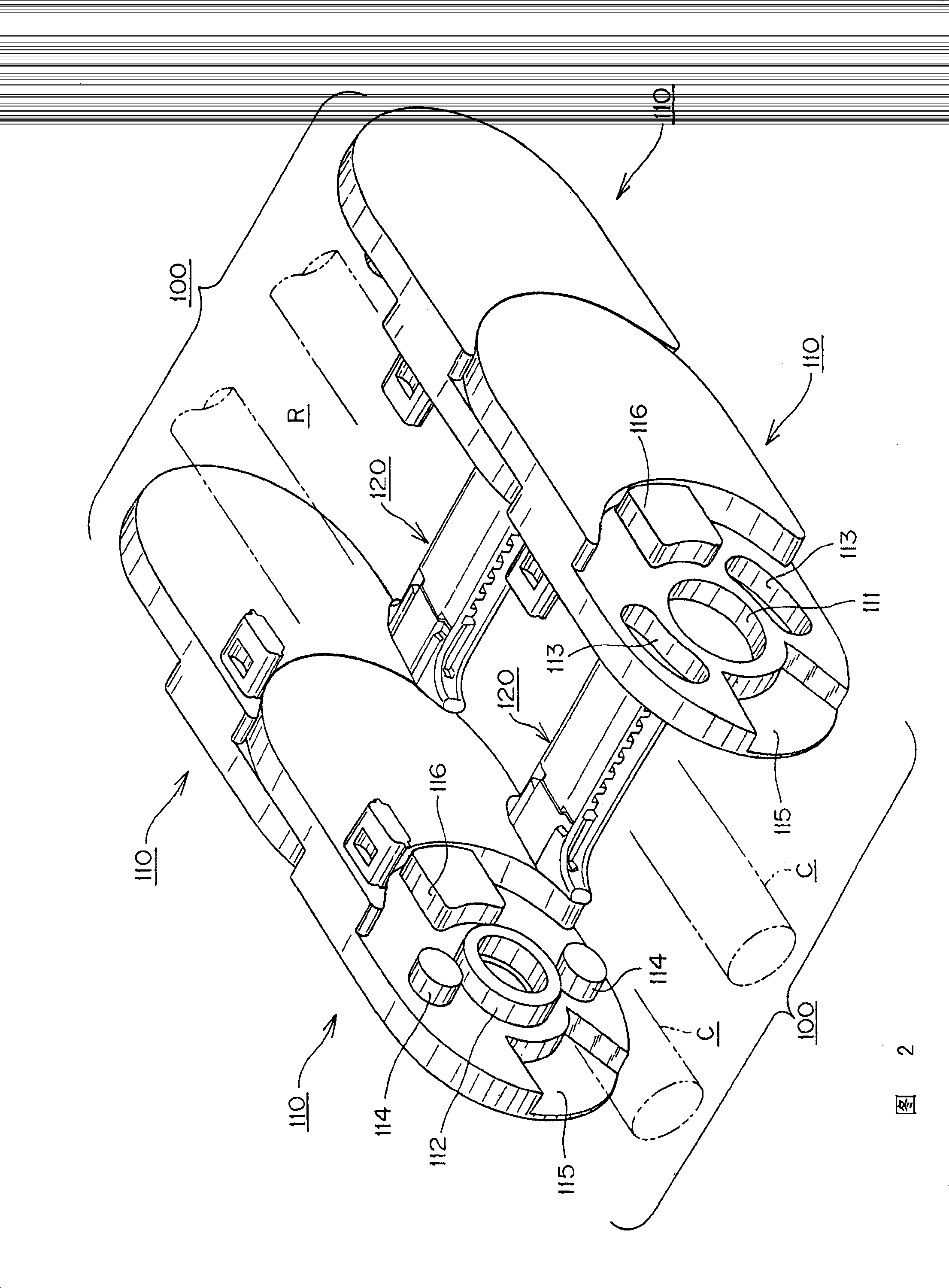
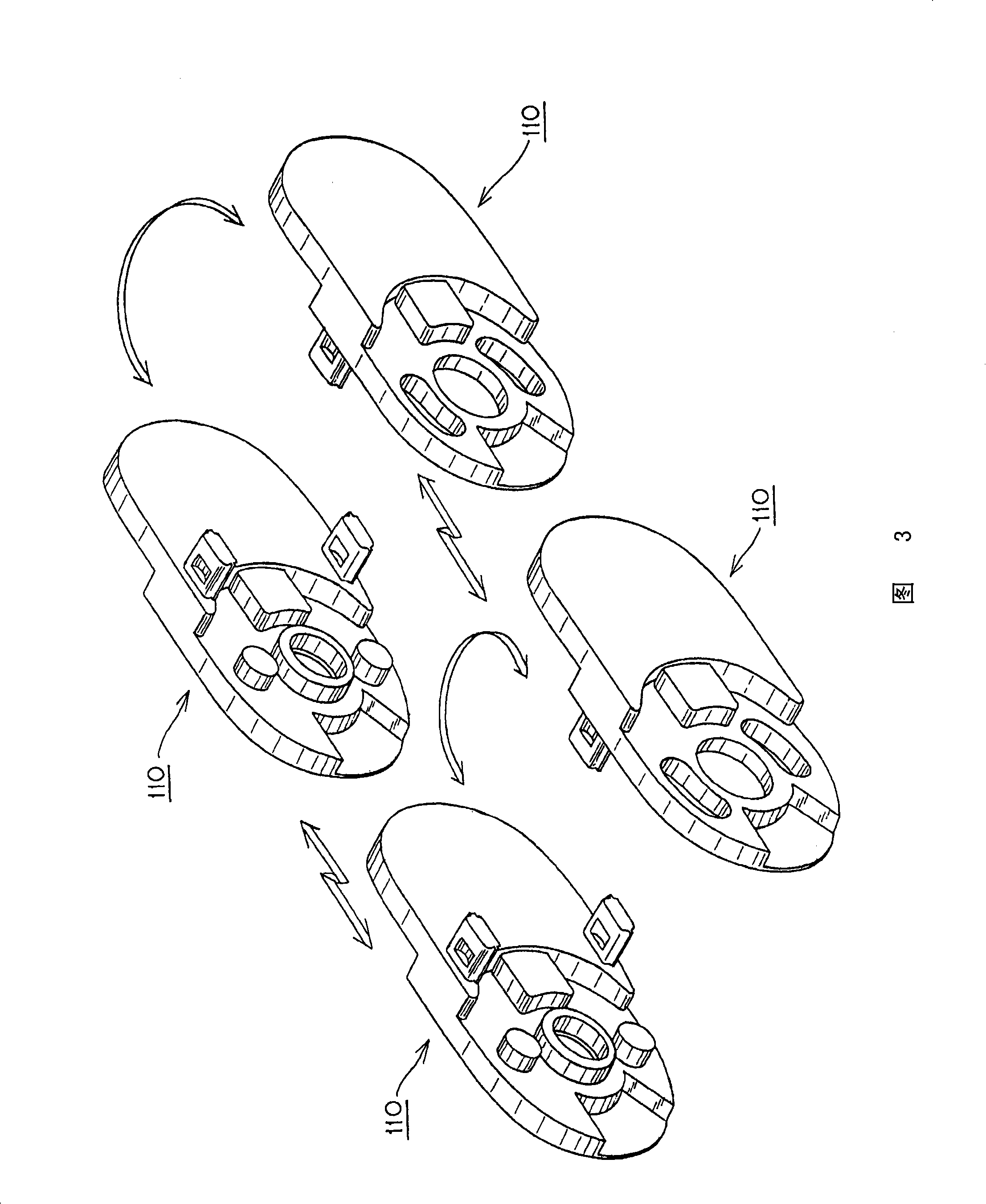
[0041] Below, refer to the attached Figure 1 to Figure 12 A cable protection and guide device according to an embodiment of the present invention will be described.

[0042] first, figure 1 It is a view of the use form of the cable protection and guiding device according to the first embodiment of the present invention, figure 2 yes means figure 1 A three-dimensional view of the connection state of the link boards in each other, image 3 It is an explanatory diagram showing the arrangement status of the link board, Figure 4 It is a perspective view of the link plate used in the first embodiment of the present invention viewed from the side of the cable storage space, Figure 5 Viewed from the outside of the cable storage space Figure 4 A perspective view of the link board shown, Figure 6 It is a perspective view of the connection state seen when the link plate is partially cut away from the cable storage space side, Figure 7It is a perspective view of the connect...


PUM


Abstract

A cable protection and guide device comprising a number of pairs of right and left spaced side plates articulately connected to each other in a longitudinal direction wherein the plates are identical and interchangeable. Each of the link plates includes an arc shaped concavity, a convex portion and, the convex portion of the next adjacent link plate interengages the arc shaped concavity of the link plate. The arc shaped concavity includes a warp limiting lock groove and the convex portion includes an arc-shaped warp limiting lock piece The arc-shaped warp limiting lock piece of the convex portion interengages the arc-shaped warp-up limiting groove of the arc shaped concavity of link plate so that the warping of the link plates is substantially eliminated. The manufacturing cost for a single link plate used in a cable protection and guide device is reduced by half.

Description

technical field [0001] The invention relates to a cable protection and guiding device, which can safely and reliably protect and guide cables and flexible cables such as hydraulic hoses, pneumatic hoses, optical fibers, etc. These cables are used in working machines, electronic equipment, and industrial robots , Conveying machinery and other industrial machinery, power supply, signal transmission, etc. to these moving machinery or the movable parts of the machinery. Background technique [0002] In the past, as such a cable protection and guiding device, there is a device in which a plurality of link frames are connected in the cable length direction. The connecting plates on the curved outer peripheral side and the curved inner peripheral side of the link plate are configured (for example, refer to Patent Document 1). [0003] Patent Document 1: Japanese Unexamined Patent Publication No. 2007-10087 (page 1, figure 2 ) [0004] However, there is a problem in the cable pro...

Claims


Application Information

Patent Timeline
Patent Type & Authority Patents(China)
IPC IPC(8): B65H23/04F16G13/16
CPCF16G13/16H02G11/00F16G13/12
Inventor 小宫庄一郎松田孝之山下胜英
Owner TSUBAKIMOTO CHAIN CO
Why Eureka
Try Eureka