Cable protection and guide device

A technology for guiding devices and cables, which is applied in the installation of cables, cable arrangement between relatively moving parts, drag chains, etc., can solve the problems of manufacturing errors of left and right link plates, complicated connection and assembly operations, and obstacles to bending movements, etc. Achieve the effect of reducing production costs, simplifying parts supply management, and halving production costs

Active Publication Date: 2009-02-11
TSUBAKIMOTO CHAIN CO
View PDF1 Cites 9 Cited by
  • Summary
  • Abstract
  • Description
  • Claims
  • Application Information

AI Technical Summary

Problems solved by technology

[0004] However, there is a problem in the cable protection and guiding device of the above-mentioned Patent Document 1, that is, since it is necessary to form a pair of left and right link plates using separate molds on the left and right, the manufacturing cost of the link plate mold cannot be reduced, and it can be used in the desired production. When the shape of the link plate has a variety of functions, there is a problem in mold production that often doubles the production cost of the link plat

Method used


Image

  • Cable protection and guide device
  • Cable protection and guide device
  • Cable protection and guide device

Examples


Embodiment Construction

[0041] Next, the cable protection and guide device according to the embodiment of the present invention will be described with reference to the accompanying drawings 1 to 12 .

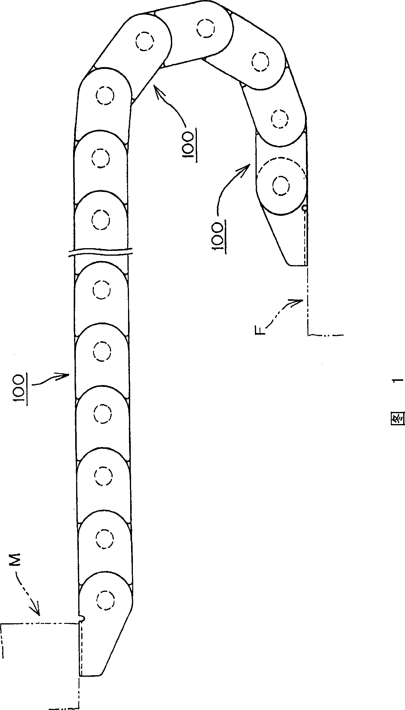
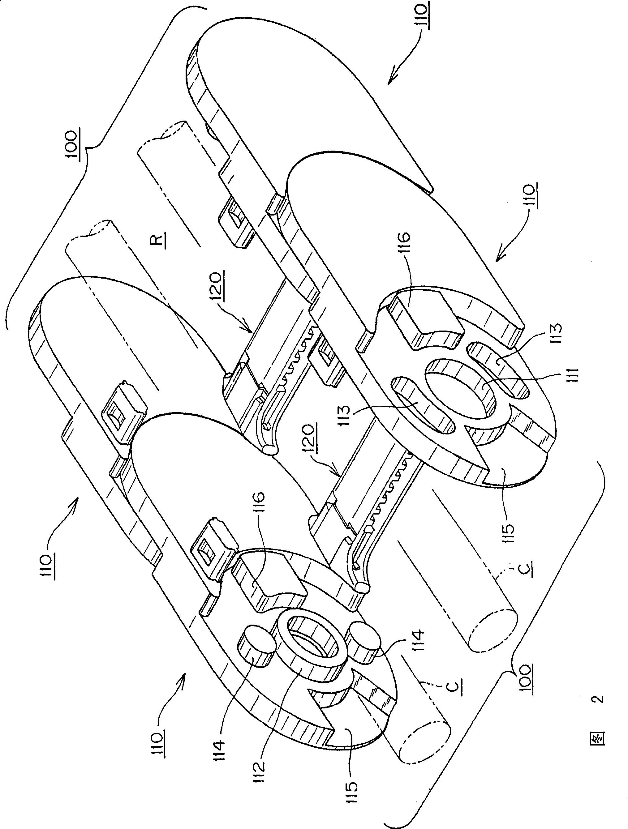
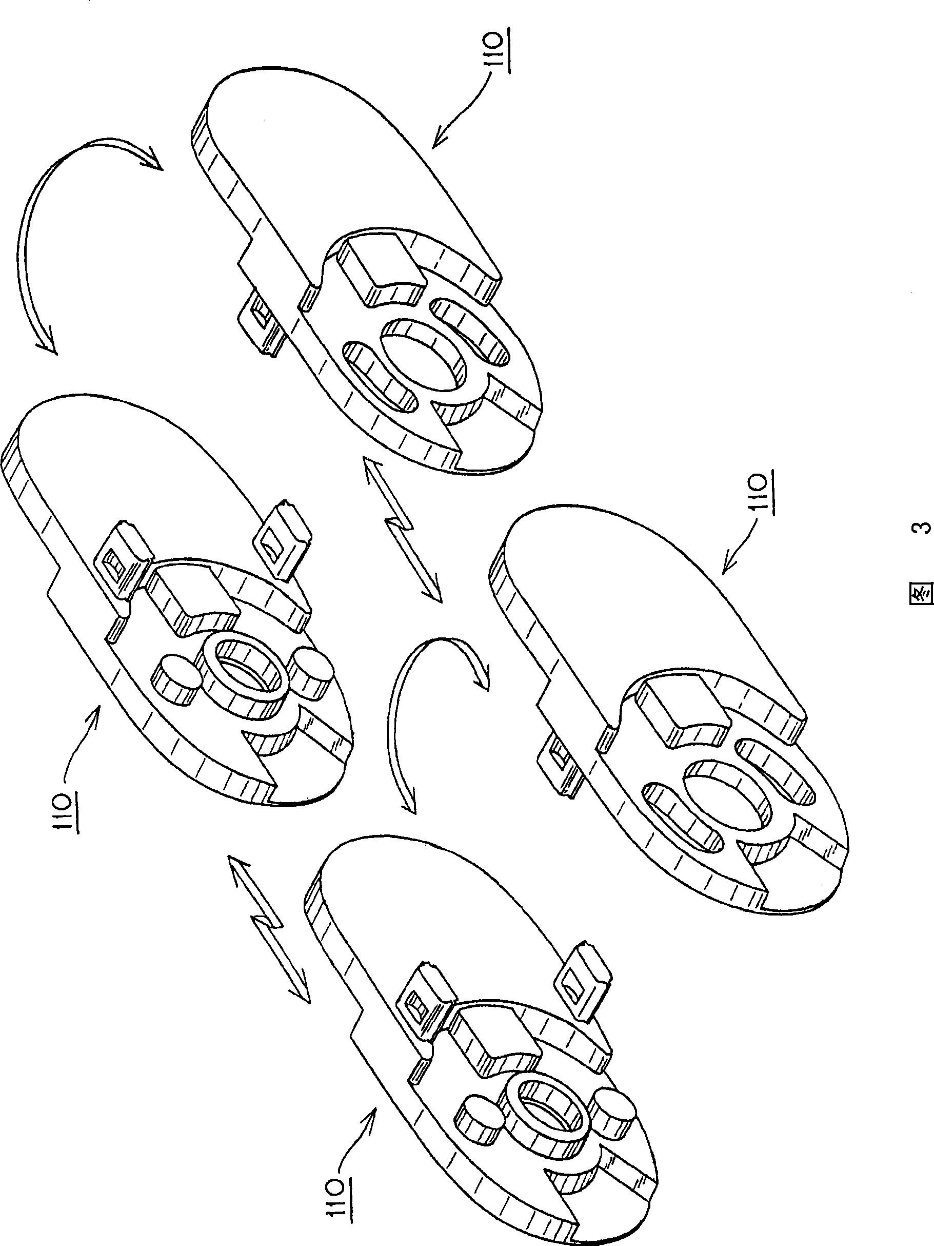
[0042] First of all, FIG. 1 is a view showing the use of the cable protection and guiding device according to the first embodiment of the present invention, FIG. 2 is a perspective view showing the connection state of the link plates in FIG. 1 , and FIG. 3 is an illustration showing the arrangement of the link plates. Fig. 4 is a perspective view of the link plate used in the first embodiment of the present invention viewed from the side of the cable storage space, and Fig. 5 is a perspective view of the link plate shown in Fig. 4 viewed from the outside of the cable storage space, and Fig. 6 is A perspective view of the connection state seen when the link plate is partially cut away from the side of the cable storage space, Fig. 7 is a perspective view of the connection state seen when the link plate i...


PUM


Abstract

The present invention provides a cable protection and guide device. The manufacturing cost for a single link plate used in the cable protection and guide device is reduced by half, link plates have no manufacturing error when connected and assembled and can be assembled randomly at front, back, left and right sides, and the component supply and management is convenient. In the cable protection and guide device (100), connecting plates (120) are arranged cross the curved inner circumference and the curved outer circumference of the right and left spaced link plates (110, 110), and a cable accommodating space (R) protects and guides cables (C) under connection state, wherein a plurality of link plates are connected by curving connecting pins and connecting pin openings at the eccentric positions of the front side portion and the rear side portion along the longitudinal direction of cables. The link plate forms a single plate, such that the link plate can be configured at the front, back, left and right sides of the longitudinal direction of cables.

Description

technical field [0001] The invention relates to a cable protection and guiding device, which can safely and reliably protect and guide cables and flexible cables such as hydraulic hoses, pneumatic hoses, optical fibers, etc. These cables are used in working machines, electronic equipment, and industrial robots , Conveying machinery and other industrial machinery, power supply, signal transmission, etc. to these moving machinery or the movable parts of the machinery. Background technique [0002] In the past, as such a cable protection and guiding device, there is a device in which a plurality of link frames are connected in the cable length direction. The connecting plates on the curved outer peripheral side and the curved inner peripheral side of the link plate are configured (for example, refer to Patent Document 1). [0003] Patent Document 1: Japanese Unexamined Patent Publication No. 2007-10087 (page 1, FIG. 2 ) [0004] However, there is a problem in the cable protec...

Claims


Application Information

Patent Timeline
IPC IPC(8): F16G13/16
CPCF16G13/16H02G11/00F16G13/12
Inventor 小宫庄一郎松田孝之山下胜英
Owner TSUBAKIMOTO CHAIN CO
Why Eureka
Try Eureka