Detection device for roughness of surface

A surface roughness and detection device technology, applied in the field of measurement, can solve the problems of increasing the production cost of the instrument, and achieve the effects of fast measurement speed, cost reduction, and insensitivity to environmental temperature changes

Inactive Publication Date: 2011-04-20
北京时代之峰佳亿科技有限责任公司
View PDF1 Cites 0 Cited by
  • Summary
  • Abstract
  • Description
  • Claims
  • Application Information

AI Technical Summary

Problems solved by technology

In order to avoid multiple reflections, it is usually necessary to add black, sophisticated and expensive light combining and absorbing devices to the detection device, which undoubtedly increases the production cost of the instrument

Method used


Image

  • Detection device for roughness of surface
  • Detection device for roughness of surface
  • Detection device for roughness of surface

Examples


Embodiment Construction

[0035] In order to make the purpose, technical solutions and advantages of the embodiments of the present invention more clear, the embodiments of the present invention will be further described in detail below in conjunction with the embodiments and the accompanying drawings. Here, the exemplary embodiments and descriptions of the present invention are used to explain the present invention, but not to limit the present invention.

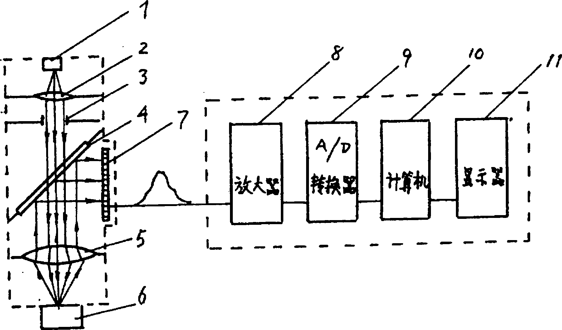
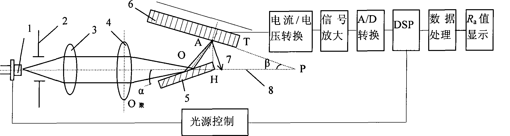
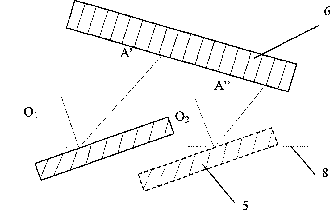
[0036] refer to Figure 2 to Figure 4 , to describe a surface roughness detection device based on optical scattering according to an embodiment of the present invention. The surface roughness detection device includes a light source unit and a photodetector 6 . The measured surface 5 is placed at an angle α to the optical axis 8 of the detection device and the photodetector 6 is placed at an angle β to said optical axis. The measured surface 5, the detector 6 and the optical axis 8 are in the same horizontal plane. The detector 6 is a photoelect...


PUM


Abstract

The invention provides a detection device for surface roughness, which comprises a light source unit and a photoelectric detector. Light which is emitted by the light source unit is radiated on the measured surface; the photoelectric detector detects a detection signal which is obtained by the light which is reflected by the measured surface; the measured surface, a light shaft of the detection device and the photoelectric detector are positioned in a same plane; the measured surface is arranged by forming a first angle with the light shaft; and the photoelectric detector is arranged by forming a second angle with the light shaft, thereby preventing the light from being reflected back to the measured surface from the photoelectric detector. The detection device of surface roughness can not only avoid the impacts of the reflected light on the measurement result, but can also reduce an absorption device and further reduce the costs.

Description

technical field [0001] The invention relates to the measurement field, in particular to a surface roughness detection device based on optical scattering. Background technique [0002] Surface roughness is the most commonly used parameter to describe the surface micro-topography, which reflects the micro-geometric shape error of the workpiece surface. In the precision machining and manufacturing industry, as the requirements for the surface quality of machined parts are getting higher and higher, the accurate measurement of the surface roughness of parts is particularly important. [0003] The mechanical stylus measurement method is to place a diamond stylus with a width of several microns vertically on the surface to be measured and move it laterally. The stylus moves vertically along with the contour shape of the surface, and converts the tiny displacement into an electrical signal and processes it to obtain the surface roughness value. The measurement accuracy of this me...

Claims


Application Information

Patent Timeline
Patent Type & Authority Patents(China)
IPC IPC(8): G01B11/30
Inventor 李粉兰段海峰郝建国许祖茂李俊国
Owner 北京时代之峰佳亿科技有限责任公司
Why Eureka
Try Eureka