High-torsion universal joint structure

A universal joint and high torque technology, applied in the field of universal joints, can solve the problems that the second universal joint 80 is unusable, cannot effectively increase the torsion resistance, and the parts of the two pivot ears are easily deformed and damaged, so as to reduce deformation damage, increase service life, and increase torque

Inactive Publication Date: 2009-02-18
胡厚飞
View PDF0 Cites 13 Cited by
  • Summary
  • Abstract
  • Description
  • Claims
  • Application Information

AI Technical Summary

Problems solved by technology

[0007] The reason for the above-mentioned defects is that when running at high speed, the part where the two pivot ears of the drive head 83 (or the sleeve joint 85) bears the torsion is located at the position of the distance H, where the lack of deformation and damage is easy to occur, resulting in the second event. The joint 80 is unsuitable for use, so the existing methods are to set rounded corners 86 at the position near the bottom surface of the second pivot ear to increase the torsion that the second pivot ear can bear
However, setting the bottom end of the second pivot lug as a rounded corner 86 cannot effectively improve its ability to withstand torsion, because the second pivot lug is still easily deformed and damaged
[0008] Simultaneously, the first kind of universal joint 90 also has the aforementioned missing existence

Method used


Image

  • High-torsion universal joint structure
  • High-torsion universal joint structure
  • High-torsion universal joint structure

Examples


Embodiment Construction

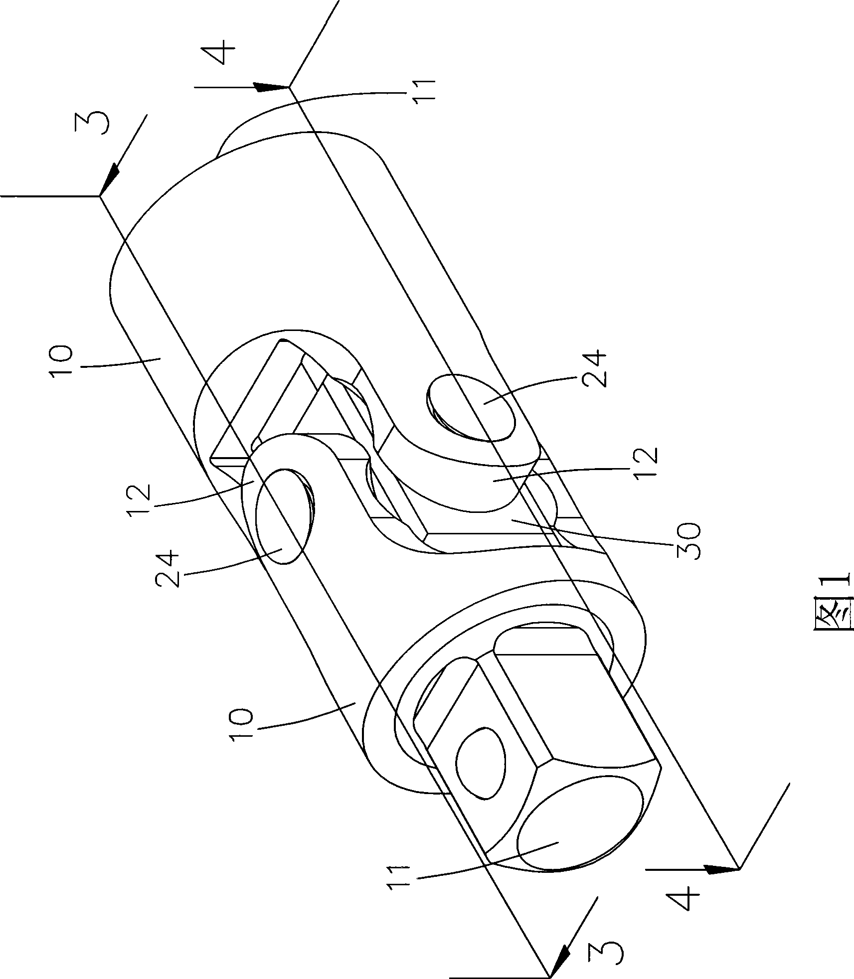
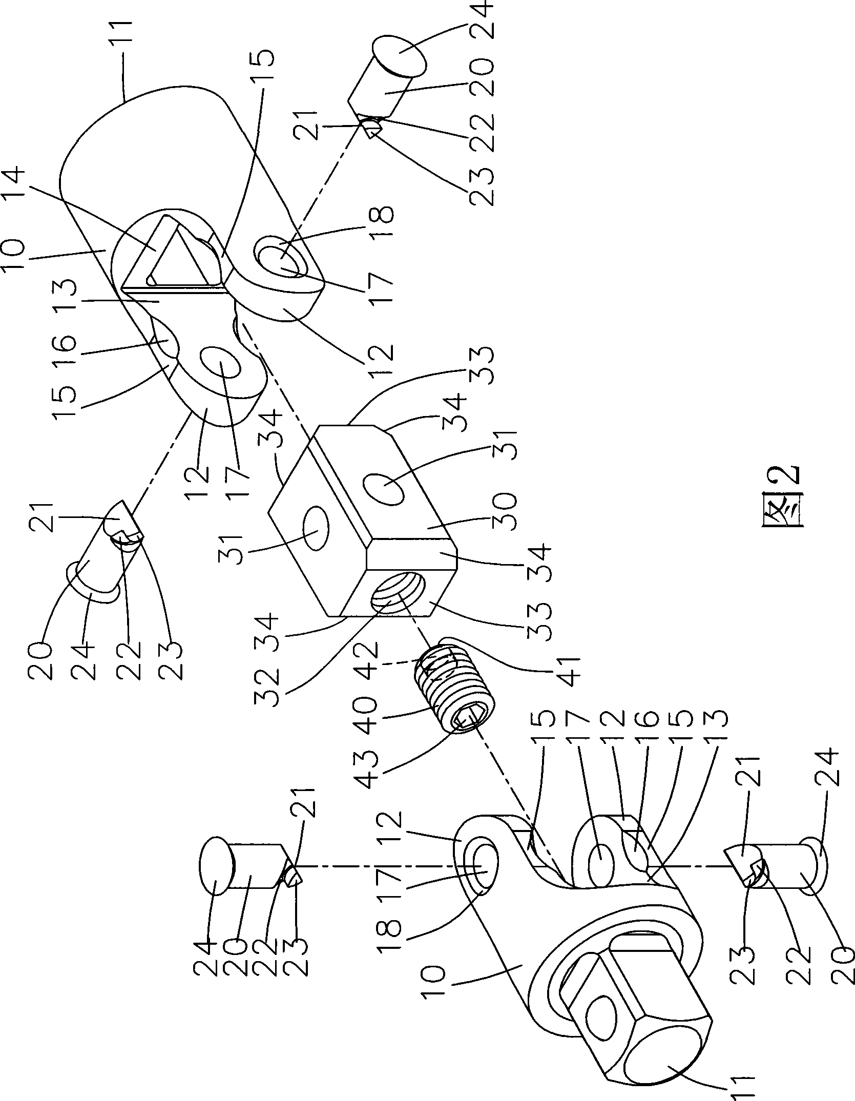
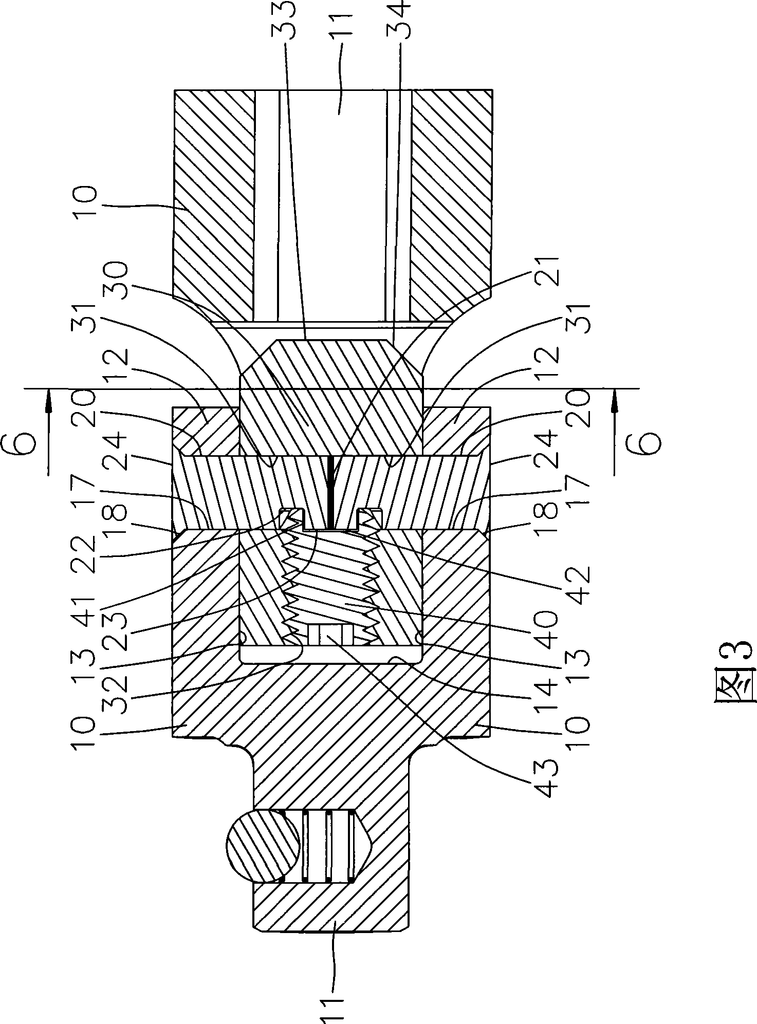
[0035] Referring to FIG. 1 and FIG. 2 , the universal joint of the present invention includes two driving parts 10 , a connecting part 30 pivotally connected between the two driving parts 10 , and a limiting part 40 disposed on the connecting part 30 . A shaft 20 is pivoted between the connecting part 30 and the two driving parts 10, and the limiting part 40 is clamped and combined with the shaft 20, so that the shaft 20 can be firmly combined in the connecting part 30, At the same time achieve the effect of detachable.

[0036] One end of the driving element 10 is provided with a coupling end 11 for connecting the driving object or the driven object. The end of the driving member 10 opposite to the connecting end 11 is provided with a pivoting end 12 . Wherein, the coupling end 11 of the driving member 10 can be configured as a sleeve shape or a square head shape, and this change can be easily accomplished by those skilled in the art.

[0037] The pivoting ends 12 of the dr...


PUM


Abstract

The invention provides a high-torsion universal joint structure which comprises two drive pieces and a connecting piece; each drive piece is provided with a pivoted end; the pivoted end is provided with a pivoted hole; the connecting piece is provided with two axial holes; axial pieces are respectively arranged between the two axial holes and the two pivoted holes to generate relative pivot-swing relation between the connecting piece and the drive pieces; two lateral surfaces of the connecting piece are arranged in the two inner surfaces of the drive pieces in the sliding way; two extension parts which extend towards the bottom of the driving pieces are respectively formed on both ends of the connecting piece to enable the pivoted ends of the driving pieces to endure large torsion and reduce the loss caused by the deformation of the pivoted ends, so as to realize the advantage of improving the service life.

Description

technical field [0001] The invention relates to a universal joint, in particular to a universal joint structure capable of withstanding high torque operation. Background technique [0002] Please refer to Figure 9 to Figure 11 , is the first conventional universal joint 90 structure, its connecting block 91 is set as a rectangular block, one end of the connecting block 91 is provided with a first pin 92 to pivotally connect a driving head 93, the connecting block 91 is opposite to the driving head 93 A second pin 94 is provided at one end to pivotally connect a socket joint 95 . The axis centers of the first pin 92 and the second pin 94 are perpendicular to each other but do not intersect each other, so that when the driving head 93 and the sleeve joint 95 are manually rotated, the allowable working angle range is relatively large. [0003] However, since the axis centers of the first pin 92 and the second pin 94 do not intersect, when the drive head 93 and the sleeve join...

Claims


Application Information

Patent Timeline
Patent Type & Authority Applications(China)
IPC IPC(8): F16D3/26B25B23/00
Inventor 胡厚飞
Owner 胡厚飞
Why Eureka
Try Eureka