Busbar connection system

A busbar connection and connector technology, applied in the field of electrical systems, can solve problems such as high production costs, and achieve the effects of cost reduction, low cost, and easy assembly

Active Publication Date: 2009-02-18
TYCO ELECTRONICS NETHERLAND BV
View PDF0 Cites 34 Cited by
  • Summary
  • Abstract
  • Description
  • Claims
  • Application Information

AI Technical Summary

Problems solved by technology

However, known standard busbar systems only allow very small variations in the predetermined distance, for example 0.1 to 0.15mm
Therefore conductors and connectors must be produced and installed with high precision, which leads to high production costs

Method used


Image

  • Busbar connection system
  • Busbar connection system
  • Busbar connection system

Examples


Embodiment Construction

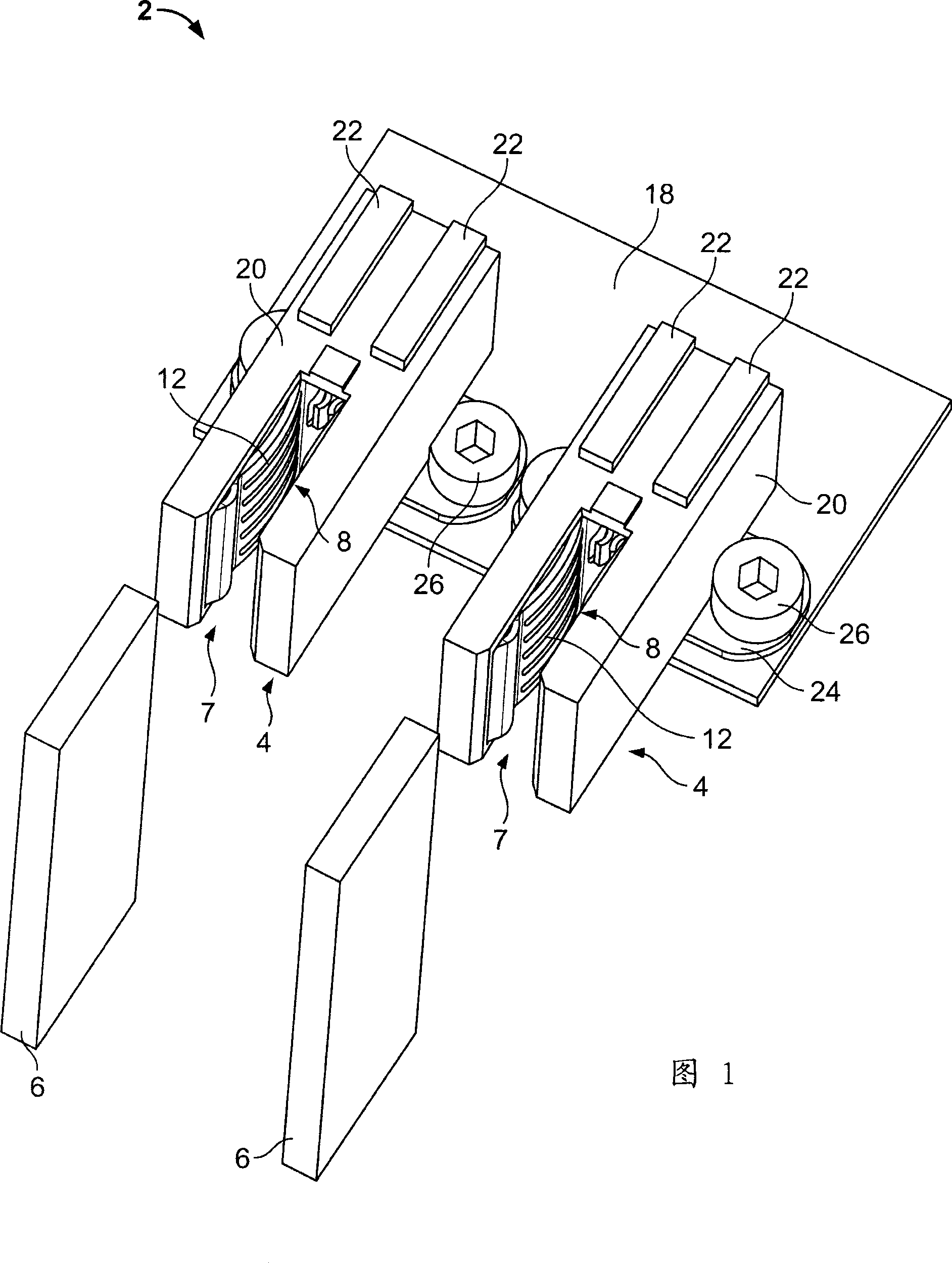
[0030] FIG. 1 shows a schematic perspective view of an exemplary busbar connection system 2 according to the invention. The busbar connection system 2 comprises two pluggable connectors 4 which are fixed side by side to the printed circuit board 18 via fixings 24 and screws 26 . Alternatively, the mount 24 may be secured to the printed circuit board 18 by press-fit contacts or soldering. Each connector 4 has a U-shape with an opening 7 opening forward away from the printed circuit board 18 . Contact members 8 are arranged on each side of each opening 7 extending substantially over the entire height of the opening. Each contact member 8 has a curved shape with an arcuate contact area 12 protruding into the opening 7 . The connectors 4 are covered by respective housings 20 made of plastic.

[0031] Two guide rails 22 are arranged on the rear top end of each housing 20 . Guide rails 22 are arranged to accommodate corresponding protrusions (not visible) formed on the top end o...


PUM


Abstract

A busbar connection system (2) includes at least two pluggable connectors (4) spaced apart from each other, for receiving at least one of at least two conductors (6) which are spaced apart from each other with a predetermined distance. Each connector (4) includes at least one contact member (8) for contacting each conductor (6); and at least one pressing member (10) clamping the contact member (8) for providing contact force between the contact member (8) and the conductor (6). At least one of the contact member (8) and the pressing member (10) of one connector (4) is elastic along the adapting direction of the conductors (6), to compensate a bias between the distance (D1) of the conductors (6) and a predetermined distance (D0).

Description

technical field [0001] The present invention is directed to busbar connection systems and electrical systems including such busbar connection systems. Background technique [0002] Busbar connection systems are often used especially in electrical power distribution systems to distribute power from a power source to several electrical devices. Such power distribution systems generally comprise at least two conductors spaced from each other at a predetermined distance for connection to several electrical devices. Each electrical device includes at least two pluggable connectors to connect to one of the conductors respectively. The pluggable connectors of each device are spaced from each other by a predetermined distance of the two conductors of the power distribution system. The conductors are typically realized as vertical strip conductors, which are spaced apart from each other by a predetermined distance, for example about 25 mm. Due to production tolerances, the distanc...

Claims


Application Information

Patent Timeline
Patent Type & Authority Applications(China)
IPC IPC(8): H02B1/20H02G5/00H01R4/48
CPCH01R12/7088H01R13/187H01R13/6315H01R13/113H01R13/18
Inventor 罗恩·达曼
Owner TYCO ELECTRONICS NETHERLAND BV
Why Eureka
Try Eureka