Ejection condition adjustment apparatus, droplet ejecting apparatus, and ejection condition adjustment method and program

A technology for adjusting devices and conditions, which is applied in the field of spraying conditions, can solve the problems of increased production costs and reduced production rates of large heads, and achieve the effects of increasing production rates and reducing manufacturing costs

Inactive Publication Date: 2009-02-25
SONY CORP
View PDF4 Cites 22 Cited by
  • Summary
  • Abstract
  • Description
  • Claims
  • Application Information

AI Technical Summary

Problems solved by technology

That is, as the bulk length increases, bulk

Method used


Image

  • Ejection condition adjustment apparatus, droplet ejecting apparatus, and ejection condition adjustment method and program
  • Ejection condition adjustment apparatus, droplet ejecting apparatus, and ejection condition adjustment method and program
  • Ejection condition adjustment apparatus, droplet ejecting apparatus, and ejection condition adjustment method and program

Examples


Embodiment Construction

[0076] Embodiments of the present invention will now be described by taking an inkjet large head including a plurality of small heads as an example.

[0077] Elements for which no specific drawings or descriptions are given here may be realized by prior art in the relevant technical field.

[0078] The embodiments described below are merely examples, and the present invention is not limited thereto.

[0079] (A) Spray condition adjustment method

[0080] (A-1) Adjustment method suitable for monochrome inkjet head

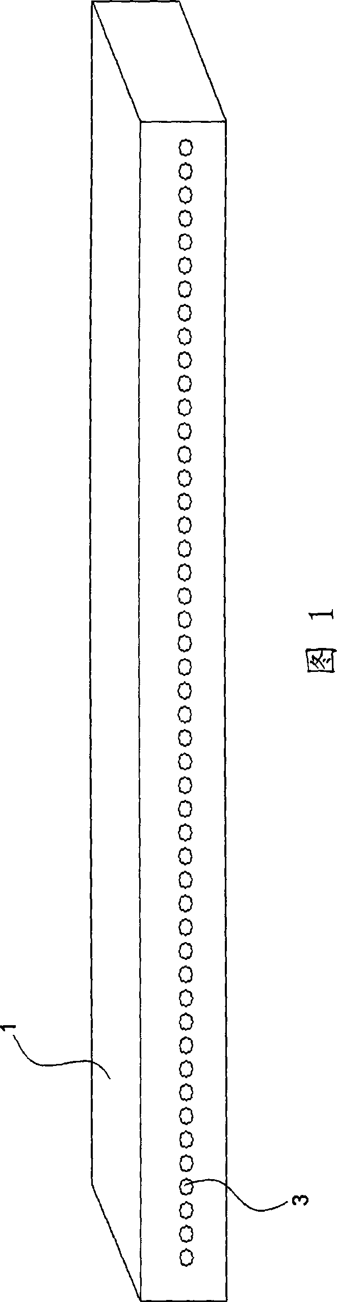
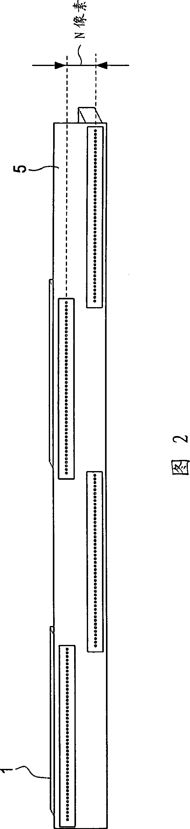
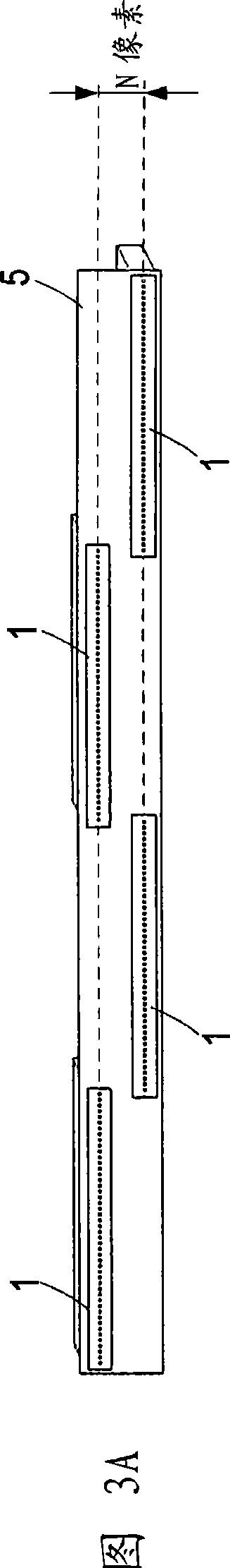
[0081] An example of a large head for monochrome printing will be described below. Fig. 11 shows an example structure of a bulk head 11 for monochrome printing. As shown in FIG. 11 , the large head 11 is provided with small heads 13 at staggered positions along the longitudinal direction. Each small head 13 has a row of a plurality of orifices 3 (dots shown on the small head 13).

[0082] (a) Example adjustment method 1

[0083] 12A to 12C show the reason why ...


PUM


Abstract

An ejection condition adjustment apparatus includes a unit configured to set, in a case where a large head to be driven includes a plurality of small heads each having a number of orifices and the small heads are disposed adjacent to one another on the large head such that regions of the respective small heads where the orifices are provided partially overlap one another, a range of orifices to be used and an ejection timing for the individual small heads such that positional shifts between adjoining ones of patterns formed by the respective small heads are minimized.

Description

technical field [0001] The present invention relates to a technique for adjusting ejection conditions of a large head including a plurality of small heads each having an ejection hole for ejecting ink or other type of liquid. According to the embodiments of the present invention, there are provided an ejection condition adjusting device, a liquid ejecting device, and an ejection condition adjusting method and program. Background technique [0002] Hereinafter, several kinds of inkjet heads will be taken as examples to illustrate the related art. FIG. 1 is an external view of an exemplary nozzle head (hereinafter referred to as "small head") 1 in which a plurality of nozzle holes 3 are arranged in a row. [0003] FIG. 2 is an example row type spray head (hereinafter referred to as "big head") 5 in which a plurality of small heads 1 are arranged at staggered positions along the longitudinal direction of the large head 5 . In the case shown in FIG. 2 , the small heads 1 adjac...

Claims


Application Information

Patent Timeline
IPC IPC(8): B41J2/145B41J2/07
CPCB41J2/155B41J29/393B41J2202/20B41J2/01B41J2/07B41J29/38
Inventor 桑原宗市
Owner SONY CORP
Why Eureka
Try Eureka