
Temperature fuse with resistor and battery protection circuit

A resistance temperature and fuse technology, applied in the field of resistance temperature fuses, can solve the problem of narrow operating power range and achieve the effect of ensuring miniaturization

Inactive Publication Date: 2013-01-09
UCHIHASHI ESTEC
View PDF1 Cites 0 Cited by
  • Summary
  • Abstract
  • Description
  • Claims
  • Application Information

AI Technical Summary

Problems solved by technology

[0010] However, in conventional thermal fuses with resistance, the lower limit of the operating power that can be operated is relatively high, and the upper limit of the operating power that can be blown by the fuse element is relatively low, and the overall operating power range is narrow.

Method used


Image

  • Temperature fuse with resistor and battery protection circuit
  • Temperature fuse with resistor and battery protection circuit
  • Temperature fuse with resistor and battery protection circuit

Examples


Embodiment Construction

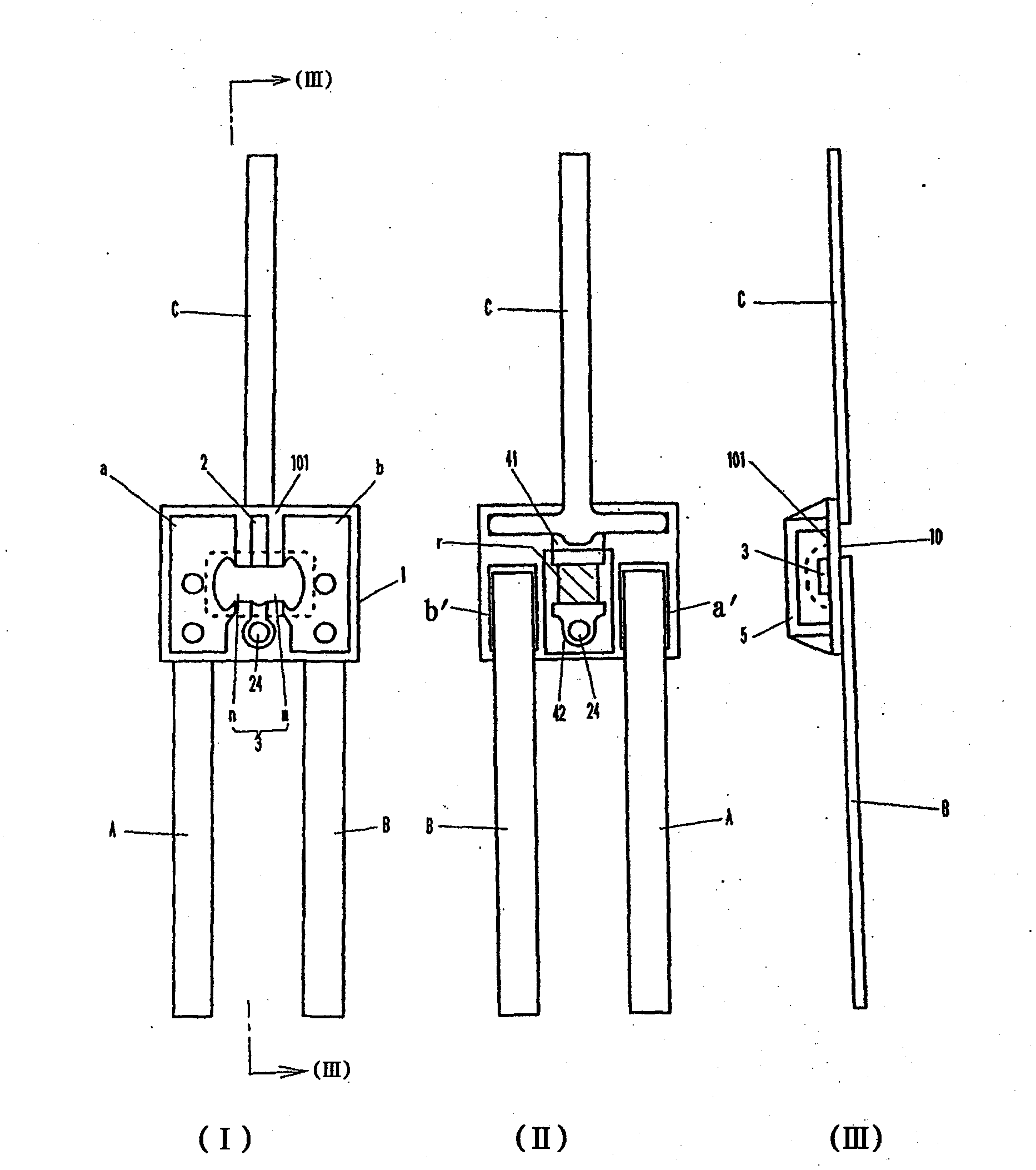
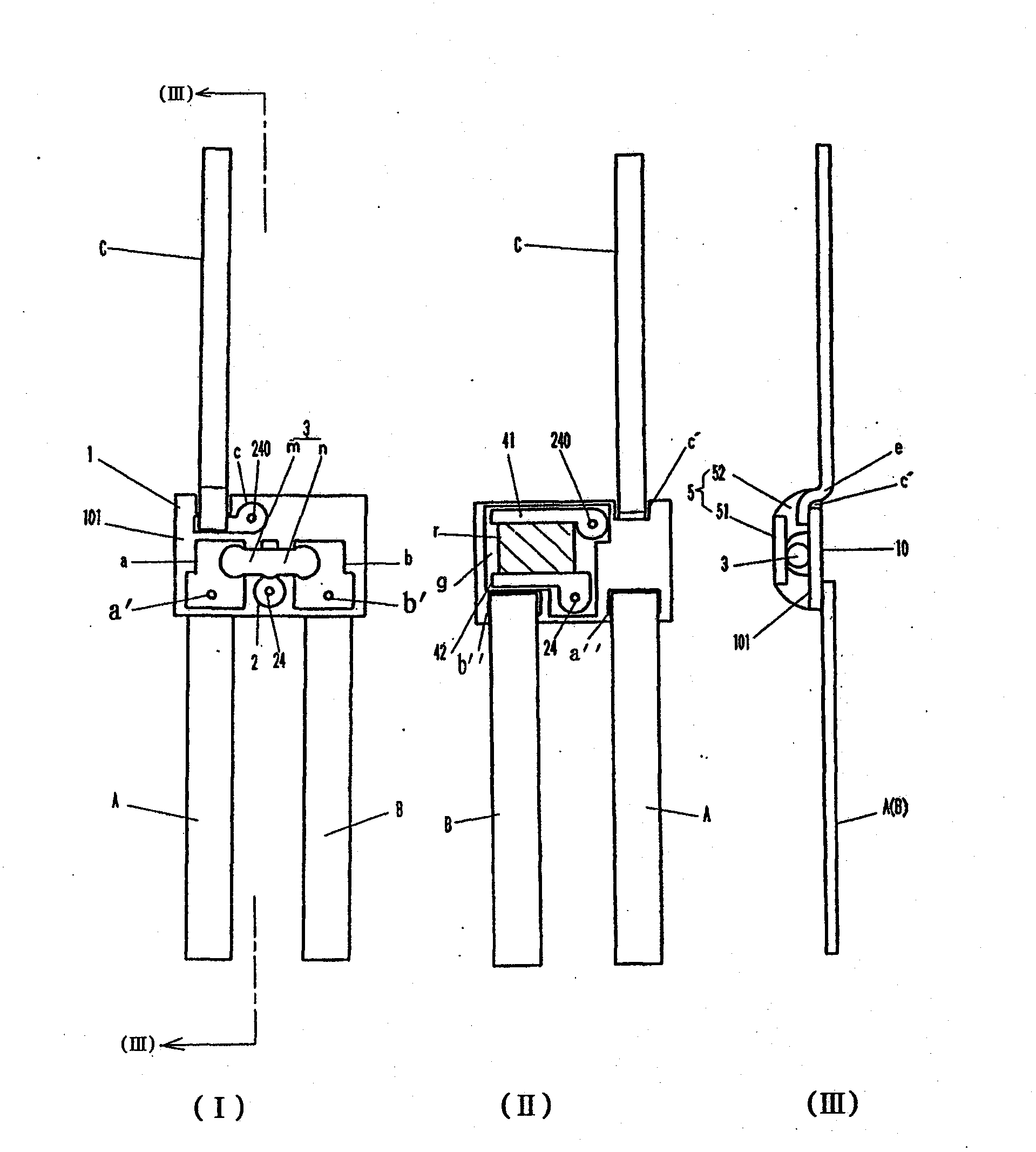
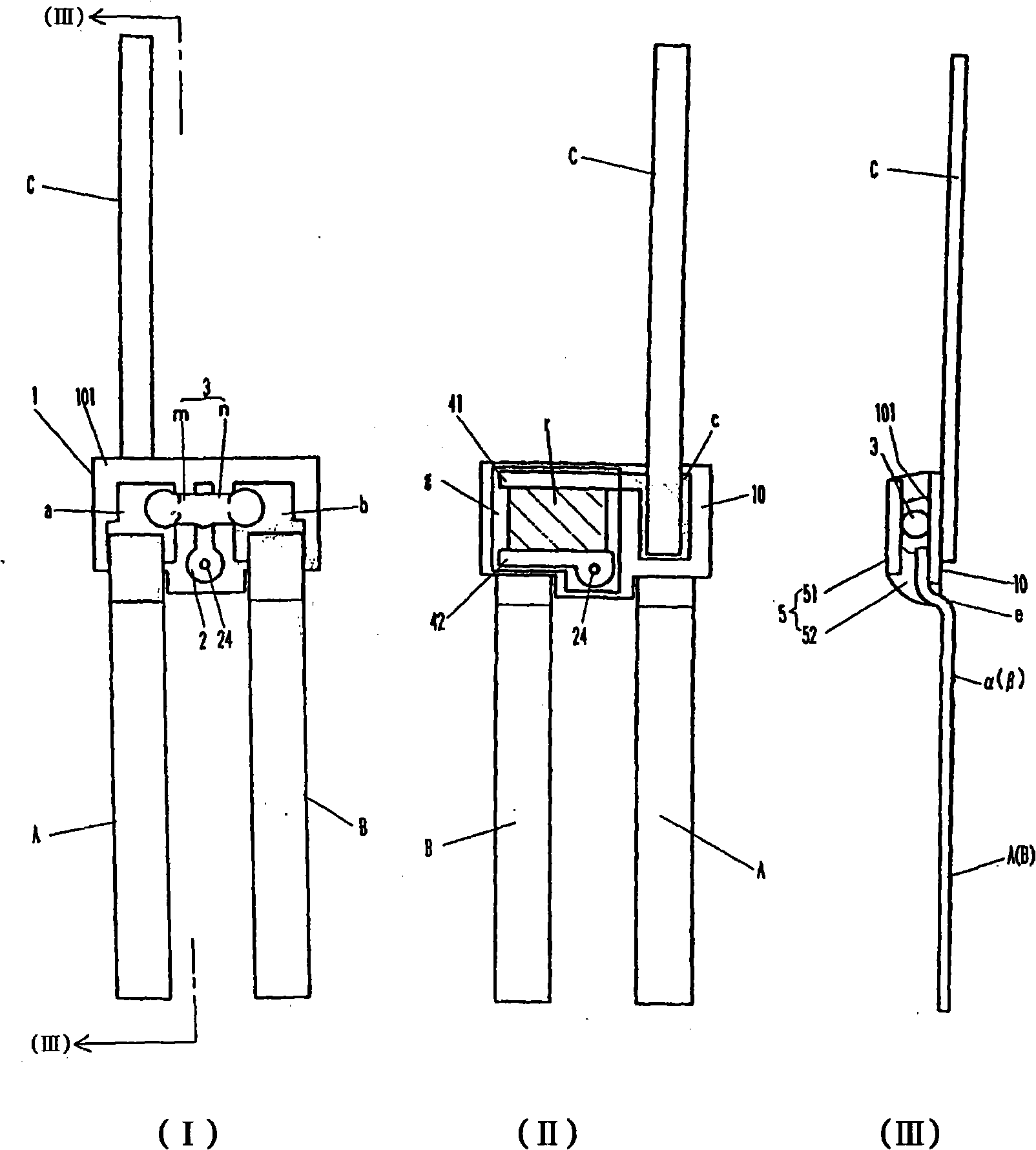
[0044] Below, while referring to the attached Figure 1 Next, an embodiment of the thermal fuse with resistance according to the present invention will be described.

[0045] figure 1 Indicates an embodiment related to technical scheme 1, figure 1 (I) is a plan view omitting an insulating sealant, figure 1 (II) is the rear view, figure 1 (III) Yes figure 1 Section III-III in (I).

[0046] exist figure 1 In (I), 1 is an insulating substrate such as a ceramic plate having good heat resistance and thermal conductivity. a and b are membrane electrodes formed on both sides of one surface of an insulating substrate, and 2 is an intermediate electrode formed by printing and firing a conductive paste such as silver paste. 3 is a fuse element, arranged across the membrane electrodes a, b on both sides and the middle membrane electrode 2, and welded at the intersection with the membrane electrodes a, b, 2. The fuse element 3 is divided into parts n and m sandwiching the in...


PUM

PropertyMeasurementUnit
thicknessaaaaaaaaaa

Abstract

A resistance attach thermal fuse is provided to realize the miniaturization of a main body and the compaction of a circuit body for protecting a secondary battery, and to melt one fuse element part authentically than the other fuse element part. A resistance attach thermal fuse has both sided membrane electrode(a, b) and in-between membrane electrode(2) on one side(101) of a substrate(1). The fuse element(3) is installed through a membrane electrode. A strip-shaped lead conductor(A, B) is welded to the membrane electrode of both sides. The one side of the substrate is covered with an insulation sealing material(5). A front and end membrane electrodes(41,42) are installed on the other side(10). The film resistance (r) is installed through the front and end membrane electrodes. One of the front and end membrane electrodes electrically is wired to the in-between membrane electrode for the fuse element. The side part (c) of the membrane electrode on the other side of both side membrane electrodes is installed. The end part of the strip-shaped lead conductor(C) is welded to the side part. The step height (e) going up to the other side of the substrate is formed in the place adjacent to the edge of the substrate of the strip-shaped lead conductor (A, B).

Description

technical field [0001] The present invention relates to a thermal fuse with resistance, which can be used, for example, as a thermal fuse with resistance mounted on a circuit body for protecting a secondary battery. Background technique [0002] In the case of using a secondary battery, such as a lithium ion battery, as a power source for a portable electronic device, the secondary battery unit and a protection circuit are housed in the package, and the protection circuit is provided with an overcharge prevention switch and an overdischarge prevention switch, It also has a fuse section that irreversibly cuts off the circuit when these switches fail. [0003] Figure 4 An example of a protection circuit for a secondary battery is shown, and a thermal fuse Ao with resistance is connected between the FET (N) for an overcharge prevention switch and the FET (M) for an overdischarge prevention switch. [0004] In this thermal fuse with resistance, the two fuse element parts n and...

Claims


Application Information

Patent Timeline
Patent Type & Authority Patents(China)
IPC IPC(8): H01H37/76H01M2/34H05K1/02
CPCY02E60/12Y02E60/10H01M2200/103H01M2220/30H01M2010/4271H01M50/581H01M50/572
Inventor 富高康彦西野智博
Owner UCHIHASHI ESTEC
Learn More