Shunt release capable of being controlled by exterior power-off protection signal

A technology of shunt release and signal control, which is applied in the direction of emergency protection device for automatic disconnection, protection for undervoltage or no voltage response, emergency protection circuit device, etc. , use restrictions and other issues, to achieve the effect of expanding the application field

Inactive Publication Date: 2009-02-25
万家盛
View PDF0 Cites 1 Cited by
  • Summary
  • Abstract
  • Description
  • Claims
  • Application Information

AI Technical Summary

Problems solved by technology

However, when it is necessary to disconnect the air switch in time in other situations, it cannot be realized.
In the event of a fire, it is generally necessary to manually cut off the power supply after the firefighters arrive at the scene.
For another example, in the process of power management, if someone illegally loosens the electronic seal of the meter box, the release cannot make the circuit breaker disconnect the circuit in time; It only acts when the current between the phase lines is unbalanced, and does not act in other cases. Therefore, the use of various circuit breakers with this kind of shunt release is greatly limited.
In addition, for this kind of circuit breaker with shunt release, after the circuit breaker operates, whether the circuit breaker is really disconnected, that is, people cannot know the working state of the circuit breaker, that is, it is not known whether the circuit breaker has really completed the circuit breaking action.
Furthermore, the previous shunt release also has the defect that the coil is easily burned when the coil is frequently tripped.
After retrieving the Chinese patents, it was found that although the Chinese patent documents disclosed some patent documents related to shunt releases, most of the circuits of these releases had the defects of complex circuits and poor versatility, that is, they could only target one or For some specific purposes, such as trip units for IC card watt-hour meters, etc.

Method used


Image

  • Shunt release capable of being controlled by exterior power-off protection signal
  • Shunt release capable of being controlled by exterior power-off protection signal
  • Shunt release capable of being controlled by exterior power-off protection signal

Examples


Embodiment Construction

[0048] The above and other technical features and advantages of the present invention will be described in more detail below in conjunction with the accompanying drawings.

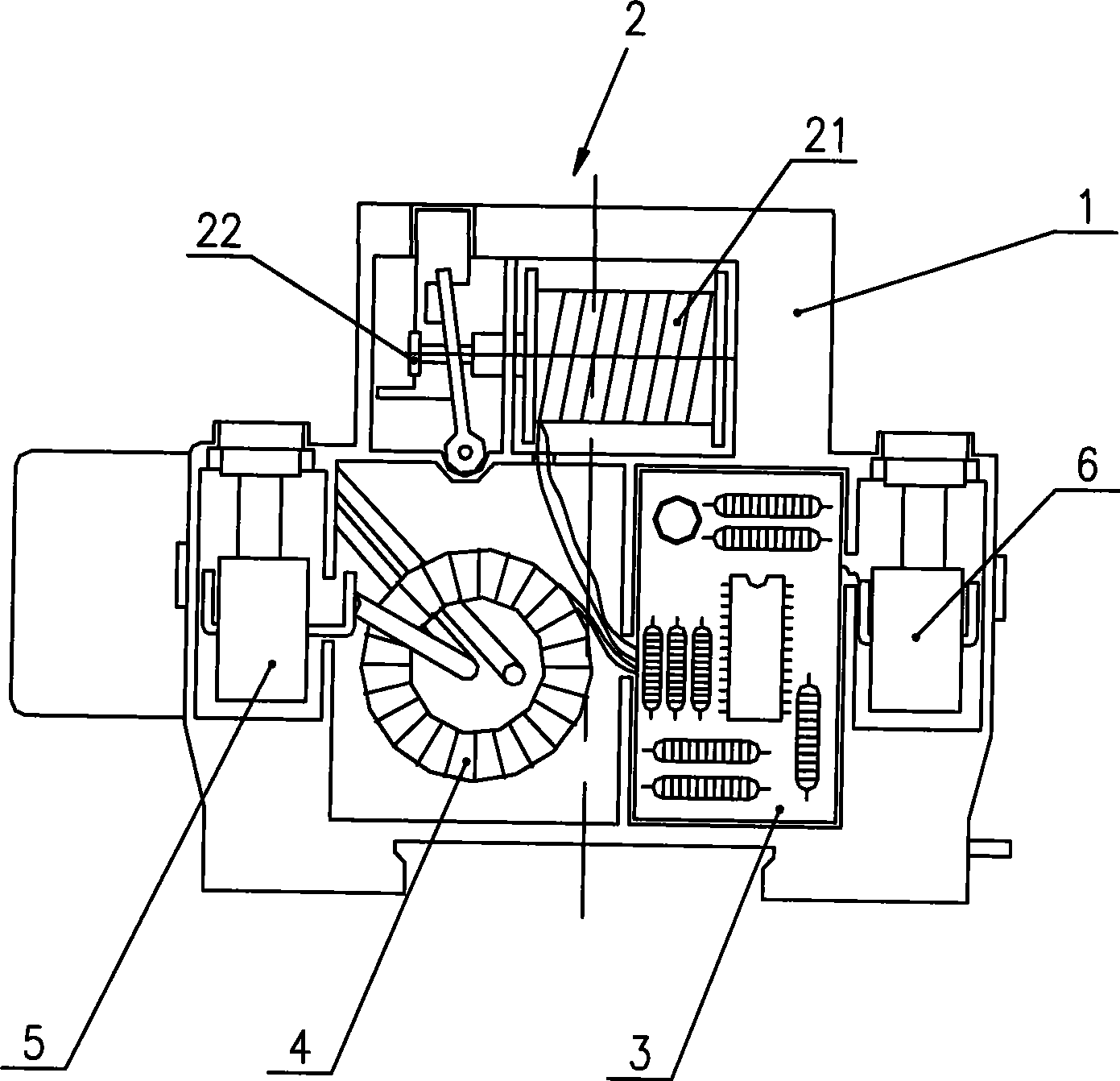
[0049] See Figure 1A , Figure 1A It is a schematic diagram of the mechanical structure of an embodiment of the shunt release that can be controlled by an external power-off protection signal in the present invention. It includes: a housing 1, an electromagnet 2 composed of a tripping coil 21, an armature 22, a control circuit 3, a current transformer 4, a power terminal 5 and a signal input terminal 6 are arranged in the housing 1. The above-mentioned signal input terminals 6 can be connected with external equipment control signals. The current transformer 4 is respectively set on the phase line L and the neutral line N, and is electrically connected with the control circuit 3, the tripping coil 21, the power terminal 5 and the signal input terminal 6, and the signal input connection Column 6 is used to...


PUM


Abstract

The invention relates to a shunt release which can be controlled by an external power-off protection signal, and is arranged on a power line. The shunt release comprises a casing, and a tripping coil and a switch control circuit which are positioned in the casing. The switch control circuit comprises an external power-off signal receiving unit used for receiving an external power-off control signal and converting a semaphore; a power supply unit used for obtaining a real-time voltage from the power line, converting the voltage to a stable voltage and supplying power to the control circuit; and a command processing unit used for receiving the semaphore so as to generate a triggering signal and enable the shunt release to conduct an off-action.

Description

technical field [0001] The invention relates to a low-voltage electric appliance product, in particular to a shunt tripper used in combination with a circuit breaker. Background technique [0002] Existing shunt releases equipped with circuit breakers, such as shunt releases equipped with leakage protection switches, also known as air switches, generally include a casing, and a tripping coil and an armature are arranged in the casing. The tripping mechanism, mutual inductance coil, control circuit and terminal posts etc. are composed. The mutual induction coil is set on the phase line and the neutral line. When the current on the phase line and the neutral line changes, the mutual induction coil will generate a current, which is input into the control circuit, and the thyristor in the control circuit is turned on. A loop is formed between the neutral line and the phase line, and the coil generates a magnetic field to make the armature move, thereby driving the circuit break...

Claims


Application Information

Patent Timeline
Patent Type & Authority Applications(China)
IPC IPC(8): H01H83/22H01H71/04H02H3/24H02H3/04H02H3/32
Inventor 万家盛汪志强
Owner 万家盛
Why Eureka
Try Eureka